Non-destructive testing with un0rick hardware
The un0rick-family boards can be used as a low-cost ultrasonic testing (UT) instrument for detecting internal defects, measuring thickness, and characterizing materials — without damaging the test piece.
This page is aimed at NDT engineers and technicians evaluating the hardware for practical inspection tasks.
What the hardware can do
| Parameter | Value | Notes |
|---|---|---|
| ADC sampling rate | 60 Msps (pic0rick) / 64 Msps (un0rick, lit3rick) | Sufficient for probes up to ~15 MHz |
| ADC resolution | 10-bit | Adequate for flaw detection; not for precision amplitude measurements |
| TGC range | 7.5 – 55.5 dB (AD8331) or 0 – 92 dB (lit3-32 with AD8332) | Programmable gain curve compensates for depth attenuation |
| Pulse type | Three-level bipolar (MD1210 + TC6320) | Suitable for standard contact and immersion transducers |
| Pulse voltage | +-25 V (pic0rick HV board) / up to +-100 V (lit3rick, un0rick) | Higher voltage = deeper penetration in attenuating materials |
| TX/RX modes | Pulse-echo (single element) or through-transmission (dual path) | Remove the TX/RX jumper for dual-element operation |
| Repetition rate | Configurable, up to ~400 Hz | Adjustable via firmware |
| Data output | USB serial (pic0rick) / SPI to Raspberry Pi (un0rick, lit3rick) | Raw waveform data, post-processing on host computer |
Typical NDT applications
Thickness measurement
Measure the thickness of metal plates, pipes, or vessels by timing the back-wall echo. With a known speed of sound in the material (e.g. ~5900 m/s for steel), the thickness is:
thickness = (time_of_flight × speed_of_sound) / 2
At 60 Msps sampling, the theoretical depth resolution is approximately 0.05 mm in steel — though practical resolution depends on probe frequency, coupling quality, and signal-to-noise ratio.
Flaw detection
Detect internal cracks, voids, inclusions, or delaminations in solid materials. Internal defects produce reflections that appear between the initial pulse and the back-wall echo. The position of the reflection indicates the depth of the defect.
Material characterization
Compare attenuation, velocity, and spectral content across samples to assess material properties, grain structure, or bond quality in composite laminates.
Setup for NDT
Hardware configuration
- Board: pic0rick (recommended for new setups) or any un0rick-family board
- Probe: Use a dual-element NDT transducer for best results. Single-element probes also work for through-transmission or immersion setups
- TX/RX separation: For dual-element probes, remove the TX/RX jumper on the board to route transmit and receive paths separately
- Couplant: Use standard ultrasonic couplant gel between the probe and the test piece
Physical setup
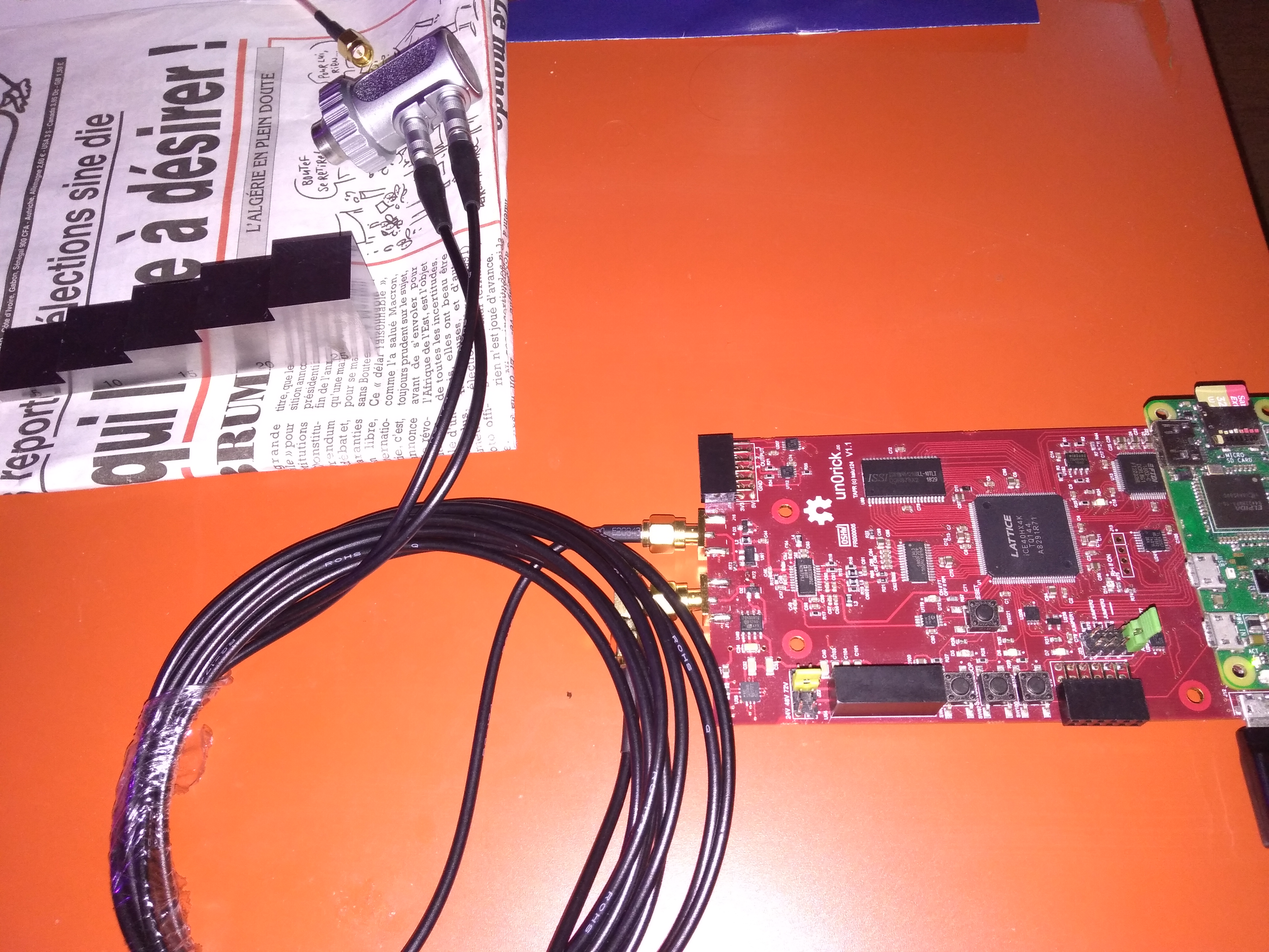
The photo above shows a dual-element transducer coupled to a steel calibration block. The block has steps of known thickness, allowing verification of measurement accuracy.
Example results
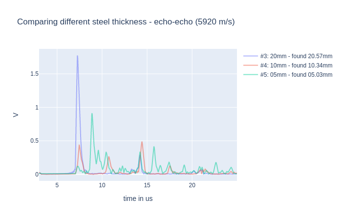
Multiple back-wall echoes at different depths
On a stepped calibration block, the back-wall echoes appear at different times corresponding to different step thicknesses:
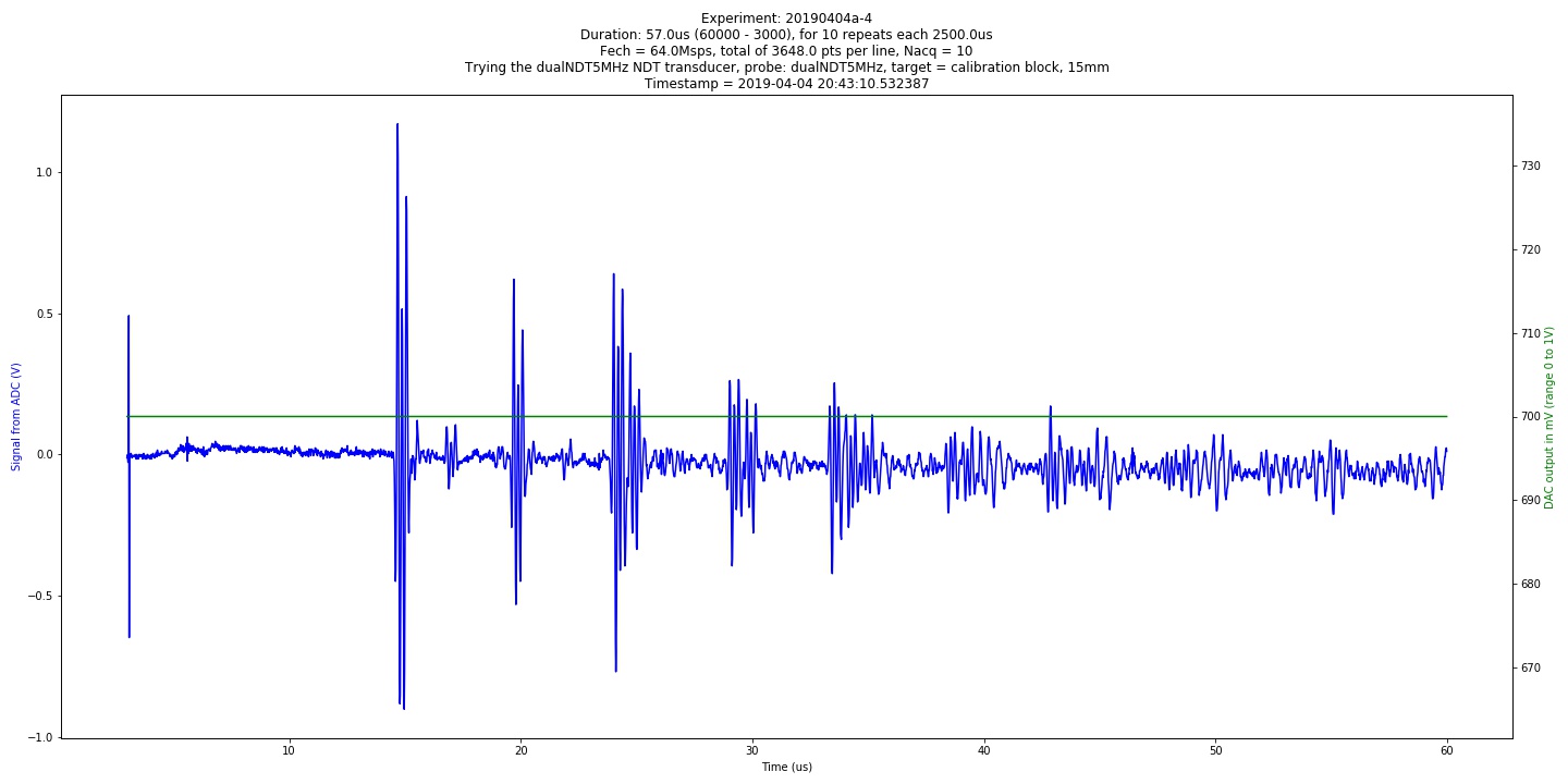
Raw A-scan signal
A typical raw acquisition from a 15 mm steel block. The initial pulse is visible at the left, followed by the back-wall echo:
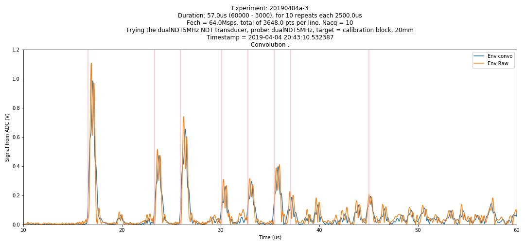
Envelope extraction
The signal envelope (analytic signal via Hilbert transform) makes it easier to identify echo peaks and measure time-of-flight:
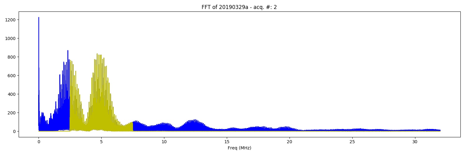
Frequency content
FFT of the echo signal shows the transducer’s effective bandwidth and center frequency in the inspection configuration:
Probe selection for NDT
The choice of transducer depends on your inspection requirements:
| Probe type | Frequency | Best for | Trade-off |
|---|---|---|---|
| Single-element contact | 1–5 MHz | Thick steel, coarse-grained materials | Good penetration, lower resolution |
| Single-element contact | 5–10 MHz | Thin plates, fine defect detection | Better resolution, less penetration |
| Dual-element (TX/RX split) | 2–5 MHz | General-purpose thickness and flaw detection | Eliminates dead zone near surface |
| Immersion transducer | 1–10 MHz | Laboratory setups, scanning applications | Requires water bath or bubbler |
Standard NDT transducers with BNC or SMA connectors can be connected directly. For probes with other connector types (Lemo, Microdot), use an appropriate adapter cable.
See also: Compatible probes for transducers that have been specifically tested with un0rick hardware.
How this compares to commercial UT instruments
The un0rick hardware is not a replacement for certified commercial flaw detectors in regulated inspection environments. It is a development and research platform. Here is an honest comparison:
| Feature | un0rick / pic0rick | Typical commercial UT instrument |
|---|---|---|
| Price | ~$100–350 (BOM cost) | $3,000–30,000+ |
| Certification | Open source hardware (OSHWA) | Calibrated, traceable, EN/ASTM compliant |
| Form factor | Dev board + computer | Handheld, battery powered, ruggedized |
| Software | Python scripts, customizable | Polished GUI, gating, DAC, reporting |
| ADC | 60 Msps, 10-bit | 100–250+ Msps, 10–12-bit |
| Gain | 48 dB (AD8331) or 92 dB (AD8332) | 80–110 dB typical |
| Pulse voltage | +-25 V (pic0rick) to +-100 V | Up to +-400 V |
| Gating / DAC curves | Manual in software | Built-in, real-time |
| Regulatory use | No — research and prototyping only | Yes — meets inspection standards |
Where un0rick makes sense for NDT: education, method development, prototyping new inspection techniques, lab research, evaluating transducers, building custom automated scanning rigs, and anywhere you need full access to raw RF data and complete control over acquisition parameters.
Where it does not: production inspection requiring regulatory compliance, field use requiring ruggedized equipment, or situations demanding high pulse voltage for deep penetration in highly attenuating materials.
Academic NDT research using un0rick hardware
Several research groups have used un0rick hardware for NDT studies:
| Year | Title | Link |
|---|---|---|
| 2025 | Nondestructive test for quality control in laboratory-scale fabrication of laminated composites | ScienceDirect |
| 2024 | NDT for internal defect detection in railway tracks (ITB thesis) | ITB |
| 2024 | UT system for quality control in lead brick fabrication | DOI |
| 2024 | Defect detection in CFRP using Pearson correlation from ultrasonic echo signals | DOI |
| 2023 | Machine-learning-based real-time photoacoustic surface crack detection | MDPI |
| 2021 | Evaluation of open source hardware for rapid prototyping of advanced UT methods (Bachelor thesis, TU Ilmenau) |
For the full list, see the Research page.
Getting started with NDT
- Follow the Getting started guide to set up your pic0rick and verify basic pulse-echo operation
- Switch to a dual-element NDT probe and remove the TX/RX jumper
- Apply couplant gel and place the probe on your test piece
- Adjust the TGC gain curve to optimize signal-to-noise ratio at your target depth
- Use the Hilbert transform (envelope) to extract echo peaks and measure time-of-flight
- Calculate thickness or defect depth from time-of-flight and the known speed of sound
Questions? Join the Slack community or check the GitHub discussions.