Get started with the pic0rick
This guide takes you from an unboxed pic0rick to your first ultrasound acquisition. No prior ultrasound or embedded systems experience is required.
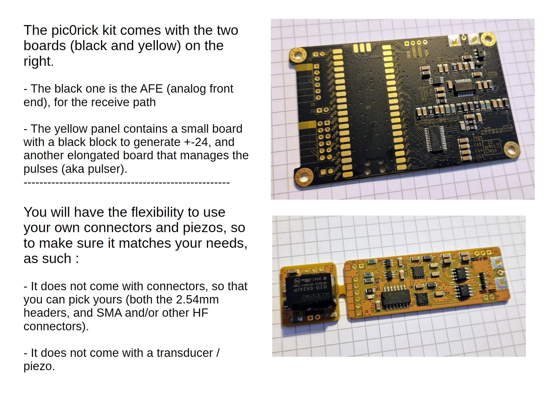
Step 1: What you need
Before you begin, make sure you have the following:
| Item | Notes |
|---|---|
| pic0rick main board | Available on Tindie or build from KiCad sources |
| Pulser board | Connects via the single PMOD header — generates the transmit pulse |
| HV board | Generates +-25V for the pulser. Plugs into the pulser board |
| A single-element ultrasound transducer | Any single-element probe in the 1–10 MHz range will work. See compatible probes for suggestions |
| SMA cable | To connect the transducer to the board’s receive SMA connector |
| SMA connectors | Coax connectors for both the pulser and the AFE boards, where to connect your cables |
| 2.54 connectors | The 2.54mm usual headers, I use them 90° angle as you can see below, female on the AFE board, male on the PMOD smaller boards |
| rp2350/rp2040 | THe usual form factor, to assemble the board and get your microcontroler of choice |
| USB cable | For power and data connection to your computer |
| A computer | Any OS with Python 3 installed (Windows, macOS, Linux) |
| A test target (optional) | A glass of water with a coin at the bottom, a metal block, or any solid object for reflection testing |
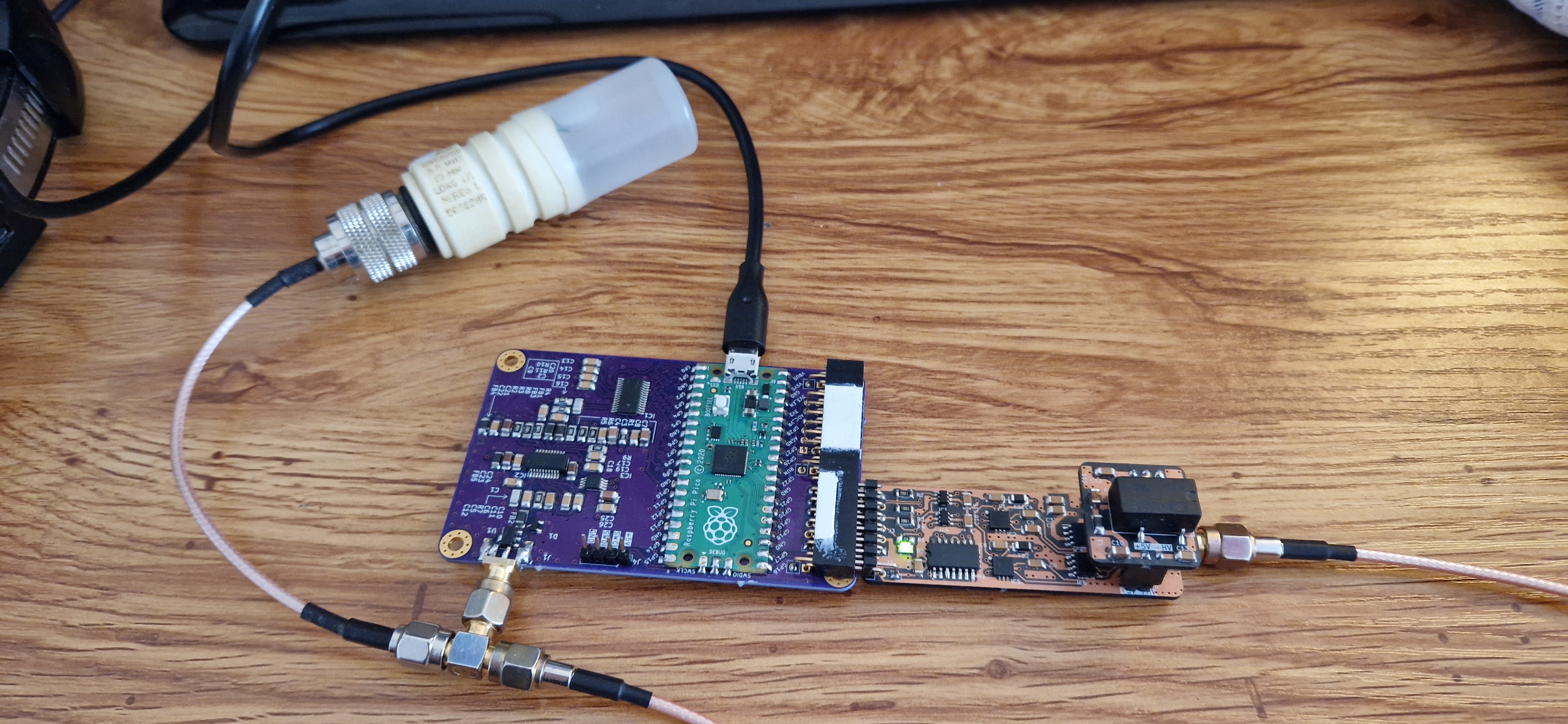
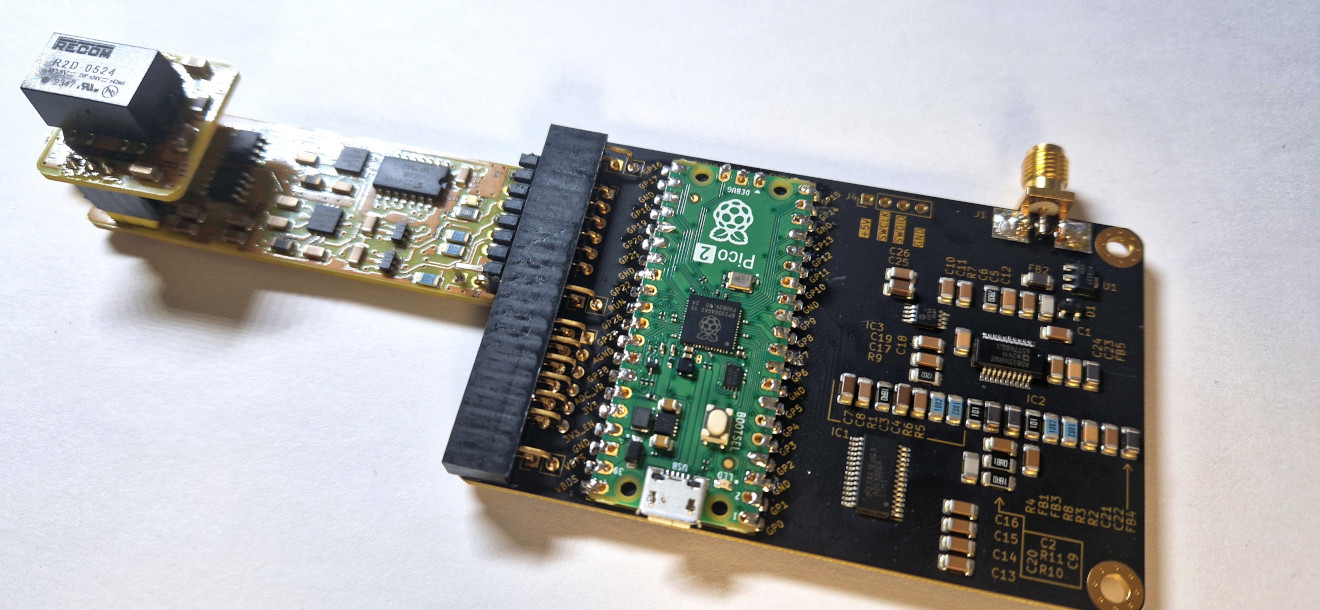
The assembled stack
The three boards connect together like this: HV board → Pulser board → pic0rick main board (via the single PMOD header). The double PMOD header on the other side can optionally connect to a VGA output or MUX extension.
Step 2: Flash the firmware
The pic0rick uses an RP2040 microcontroller, which appears as a USB mass storage device when put into boot mode.
- Enter boot mode: Hold the BOOTSEL button on the pic0rick board while plugging in the USB cable. The board should appear as a USB drive named
RPI-RP2. - Copy the firmware: Download the latest
.uf2firmware file from the pic0rick releases page and drag it onto theRPI-RP2drive. - Wait for reboot: The board will automatically reboot once the file is copied. The USB drive will disappear — this is normal.
If you prefer to build from source, the firmware code is in the pic0rick repository under the software/ directory.
Step 3: Connect the transducer
- Connect your single-element transducer to the Receive SMA connector on the pic0rick main board using an SMA cable.
- Point the transducer at your test target. For a simple first test, press the transducer against a flat metal surface or immerse it in a glass of water aimed at the bottom.
- Make sure the HV board and pulser board are connected and the full stack is powered via USB.
Step 4: Install the software
The pic0rick communicates over USB serial. You need Python 3 and a few libraries.
pip install pyserial numpy matplotlib
Clone the software repository:
git clone https://github.com/kelu124/pic0rick.git
cd pic0rick/software
Step 5: Your first acquisition
Run the acquisition script to capture your first ultrasound echo:
python pico_shell.py
This script connects to the pic0rick over serial, triggers a pulse, and captures the reflected signal through the ADC. You should see a waveform plot showing the initial pulse and any echoes from your test target.
What you should see
A typical acquisition looks like this — the large spike on the left is the transmit pulse, and the smaller peaks to the right are reflections from your target:
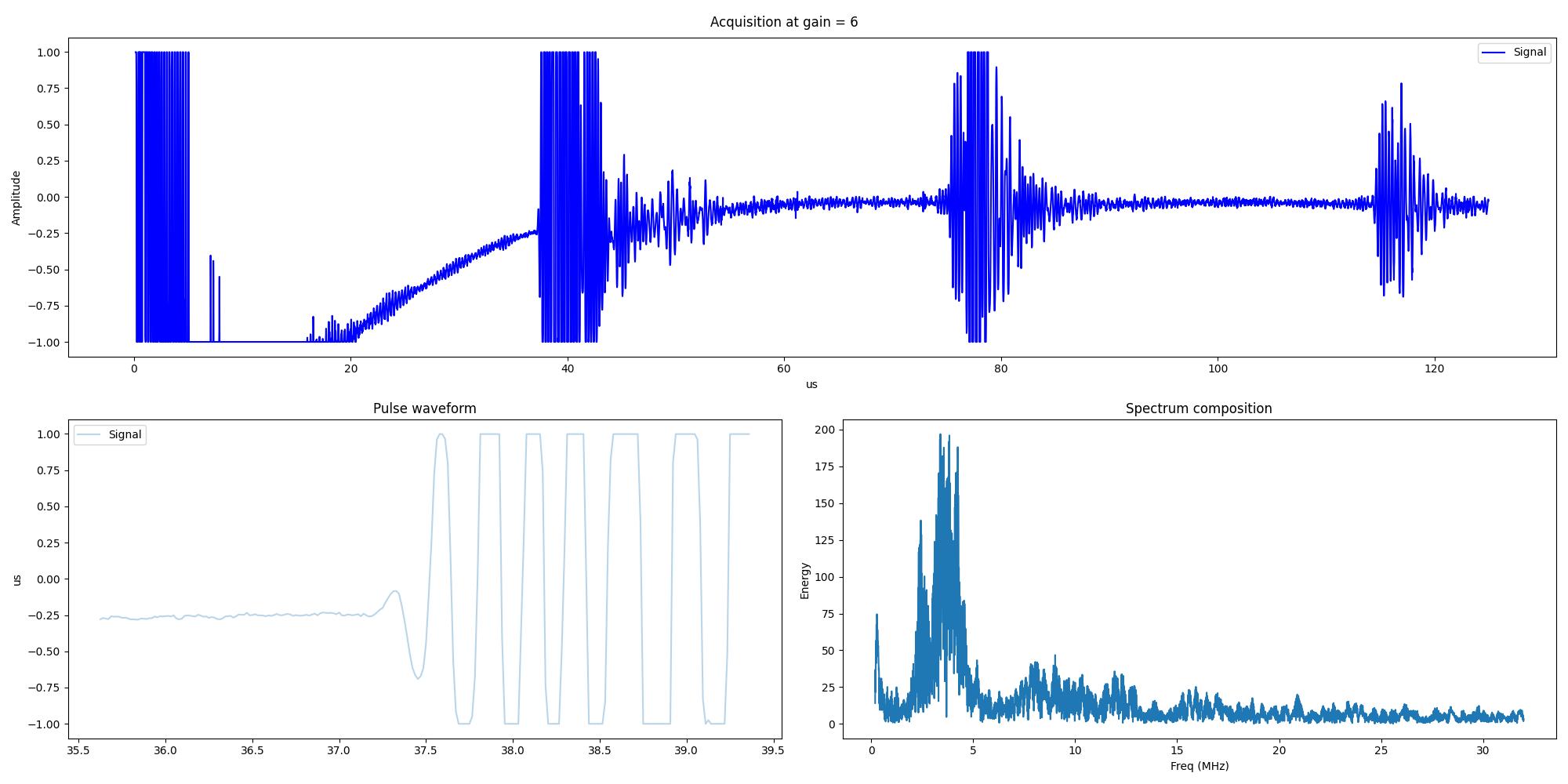
Adjusting the gain
The pic0rick features a Time-Gain Compensation (TGC) system using an AD8331 amplifier (7.5 dB to 55.5 dB range), controlled via an MCP4812 SPI DAC. You can adjust the gain curve in your acquisition script to compensate for signal attenuation at depth. The gain setting in the example above is set to 6 — try different values to see how they affect the signal.
Step 6: What’s next?
Now that you have your first acquisition working, here are some directions to explore:
- Try different use cases: Pulse-echo, NDT, or Tomography
- Add extensions: The double PMOD connector supports a VGA output for real-time display and a MUX board for driving multiple transducers
- Explore the hardware: Full KiCad design files are available if you want to modify the board
- Read the research: See how others have used the hardware in 30+ academic publications
- Join the community: Ask questions on Slack or Matrix
“Easy” troubleshooting
Board not detected over USB
- Make sure you are using a data-capable USB-C cable (some cables are charge-only).
- Try a different USB port. Some hubs may not provide enough power.
- Check that the firmware was flashed correctly — re-enter boot mode and re-flash the
.uf2file.
No echo signal visible
- Check the SMA cable connection — make sure the transducer is firmly connected.
- Verify the pulser and HV boards are connected and powered. The pulser needs the HV board to generate transmit pulses.
- Try a simpler target: press the transducer flat against a thick metal plate. You should see a strong back-wall echo.
- Increase the gain setting in your acquisition script.
Signal looks very noisy
- Make sure the HV board is properly seated on the pulser board. Loose connections introduce noise.
- Keep the USB cable and SMA cable separated — they can couple electromagnetically.
- Try averaging multiple acquisitions to improve the signal-to-noise ratio.
- If using a breadboard or loose wires for any connections, switch to direct board-to-board connections.
Serial port permission issues (Linux)
On Linux, you may need to add your user to the dialout group:
sudo usermod -aG dialout $USER
Then log out and back in for the change to take effect.
More support / troubleshooting ?
As a simple sanity check, I’d recommend trying first a basic setup: a piezo pointing straight down into a glass of water (4-5 cm depth) with a flat reflector at the bottom. This gives a clean, predictable echo that helps rule out target/coupling issues.
Then here’s the checklist, containing information I’d need to help your troubleshooting:
- HARDWARE SETUP
- Which board are you using (pic0rick, un0rick, other)?
- Which microcontroller did you solder (RP2040, RP2350)?
- A photo of your assembled setup (boards, connectors, cabling) would be very helpful.
- How are the electrical connections made (which pins, grounding)?
- EXPERIMENT CONTEXT
- What is the goal of your experiment (pulse-echo imaging, Doppler, NDT, other)?
- What signal do you expect to see?
- What gain/DAC and pulse parameters have you used?
- PIEZO / TRANSDUCER
- What transducer are you using (brand, model, central frequency)?
- How is the piezo connected to the board (SMA, BNC, other)?
- Is the piezo in contact with water, gel, or another medium?
- What is your target, and at what distance from the piezo? Is it parallel to the piezo face?
- FIRMWARE
- What firmware (.uf2 file) have you flashed? From which version of the repo?
- Have you modified the firmware in any way?
- The latest firmware is available at: https://github.com/kelu124/pic0rick/
- SOFTWARE & COMMUNICATION
- What OS are you running (Linux, Windows, Raspberry Pi OS)?
- How are you communicating with the board (serial terminal, custom scripts, Jupyter notebook)?
- Can you see the device connected (e.g., does /dev/ttyACM* appear)?
- If possible, please try cloning the repo (https://github.com/kelu124/pic0rick/) and running the example.ipynb notebook — this will help isolate whether the issue is in your code or in the hardware.
Going deeper
- pic0rick hardware details — full specs, block diagram, and PMOD extensions
- pic0rick GitHub repository — firmware source, KiCad files, and documentation
- Board comparison table — how pic0rick compares to older un0rick-family boards
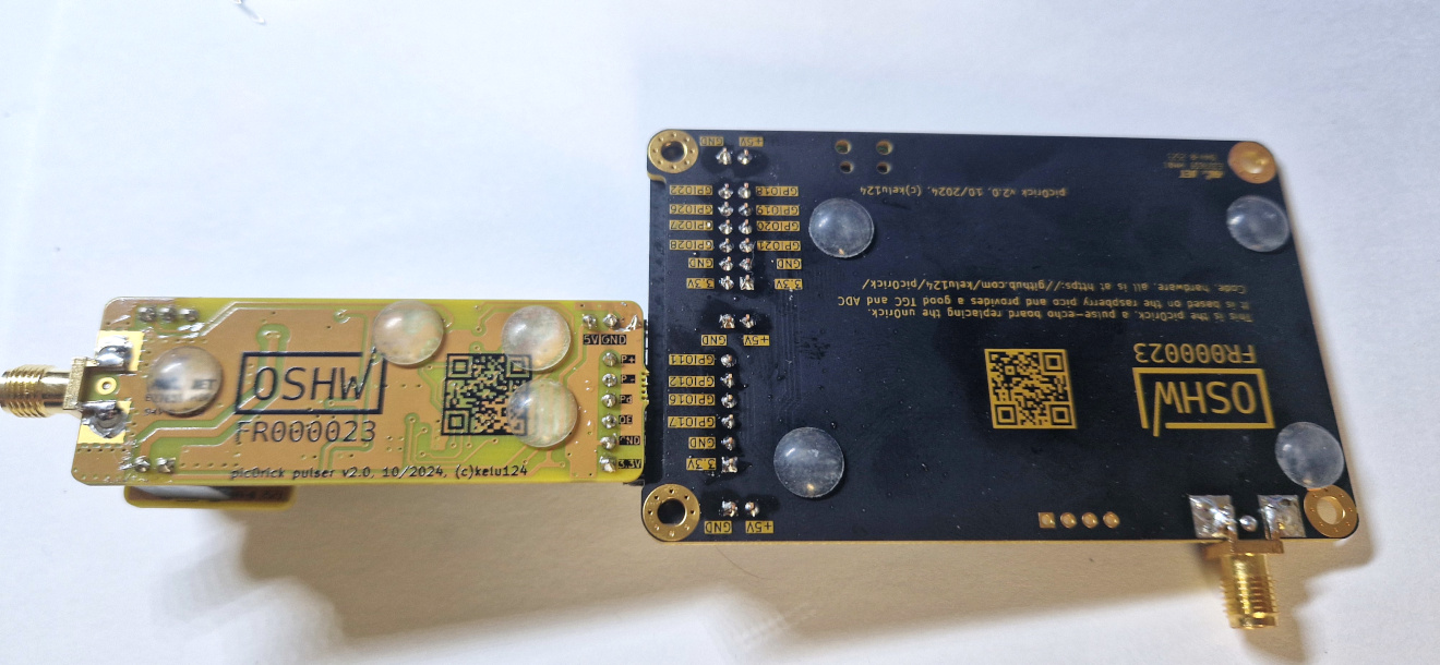
The physical assembly of the device
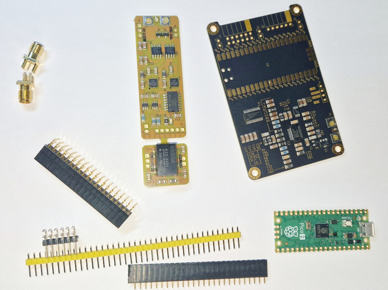
What you get :
Before assembly
You will need to get a few headers, a raspberry pico, and SMA connectors
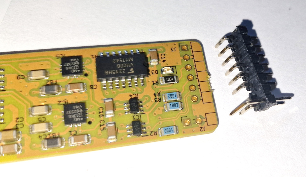
Focus on the Pulser connector
Once assembled
Top view
Bottom view