Setting up the board for Raspberry Pi acquisitions
How to connect
- Use the Rpi or Computer to connect to the FPGA
- Setup the jumper according to SPI master choice (USB or Rpi)
- Power up via a USB cable
- Configuration of the acquisition: send to FPGA the configuration registers via SPI
- Set the register EF to initiliaze memory (read and write pointers at 0)
- Start the acquisition, triging it up using the software, or with the onboard hardware trig button
- Do one SPI transaction and ignore the data received
- Read the measures via SPI
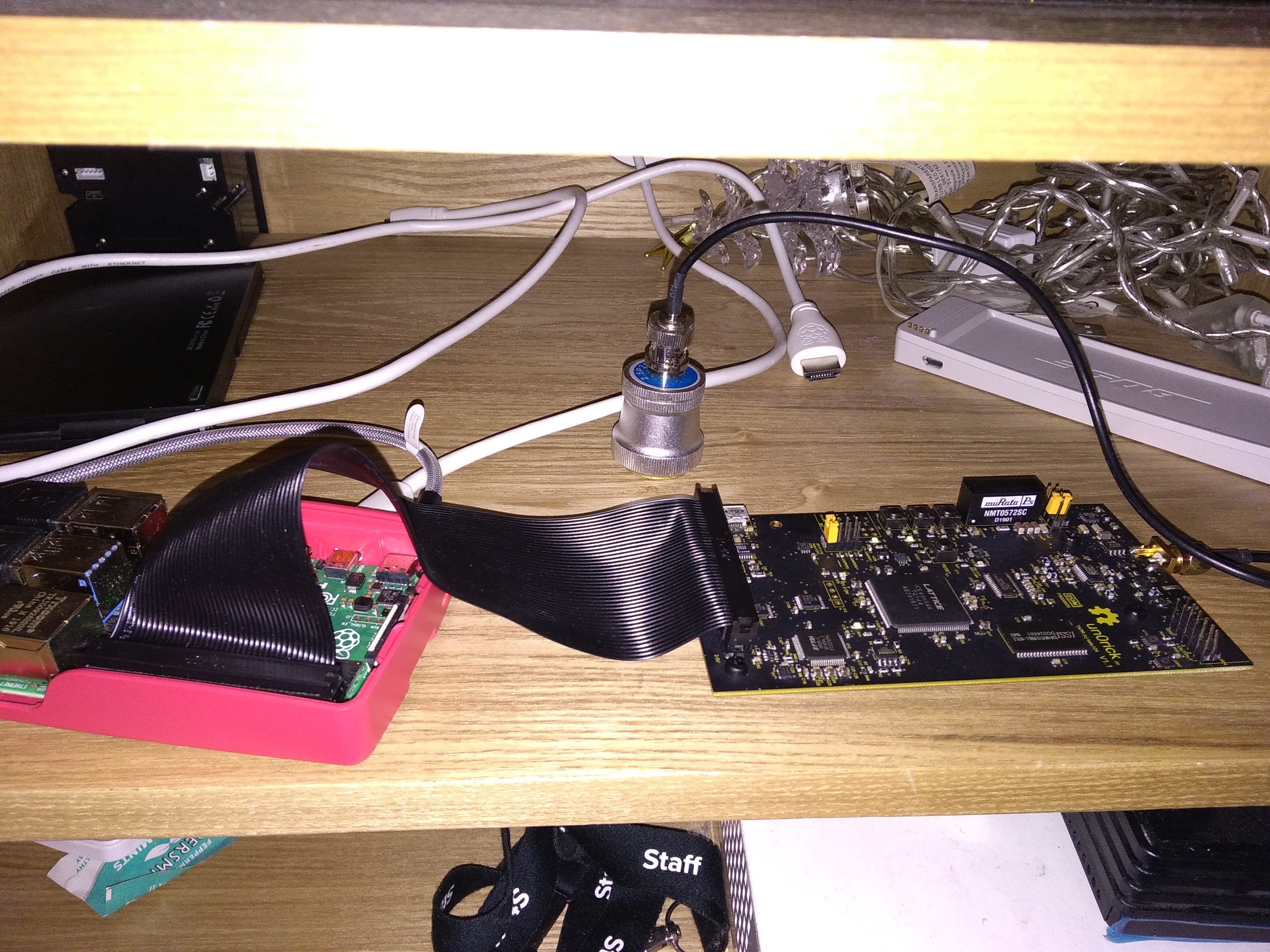
How to setup the board using only a RaspberryPi (here with RPi 4)
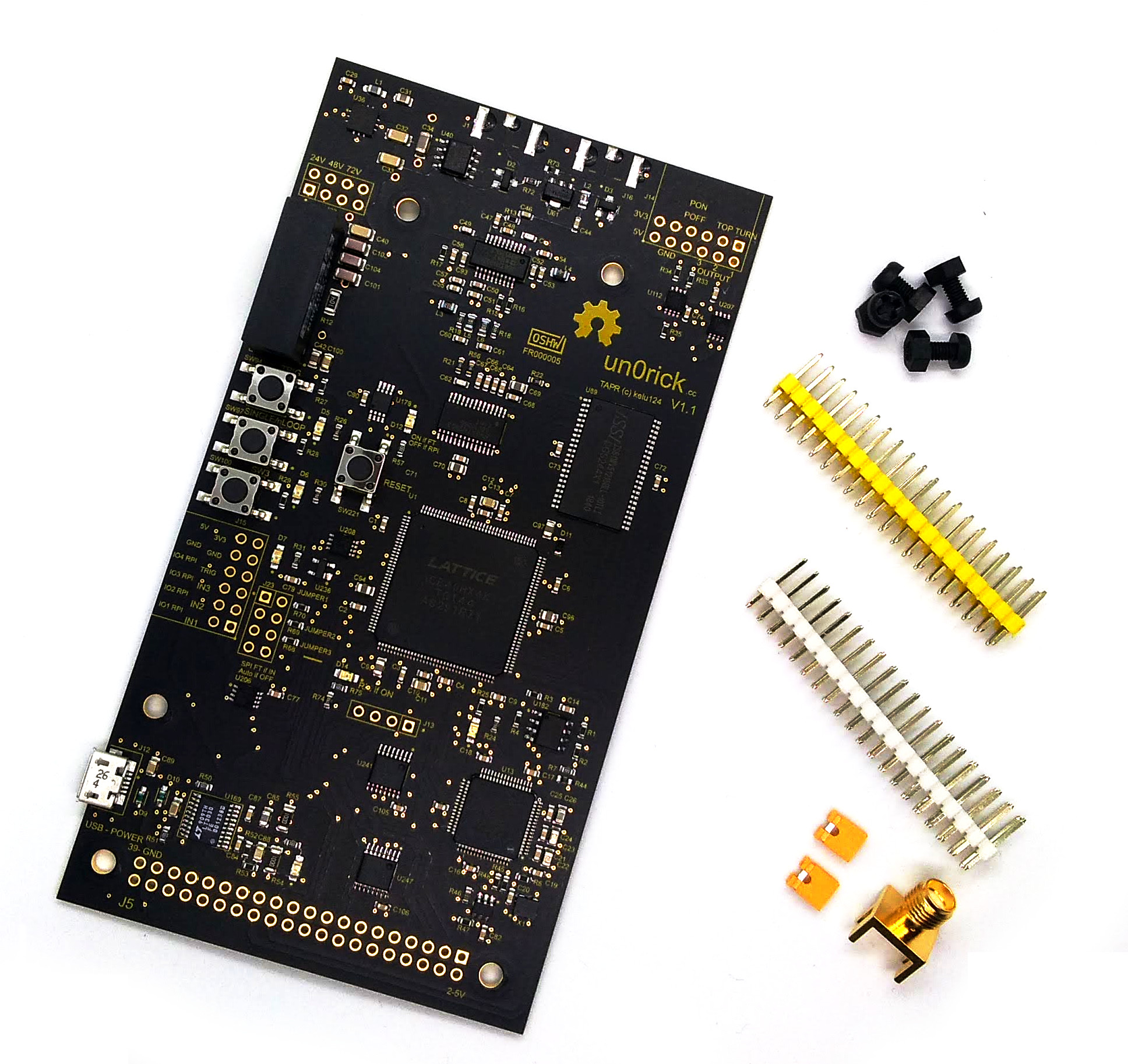
Putting the board together
Need a few feet to raise the board a bit above the ground, two 2x20 headers, and a SMA.
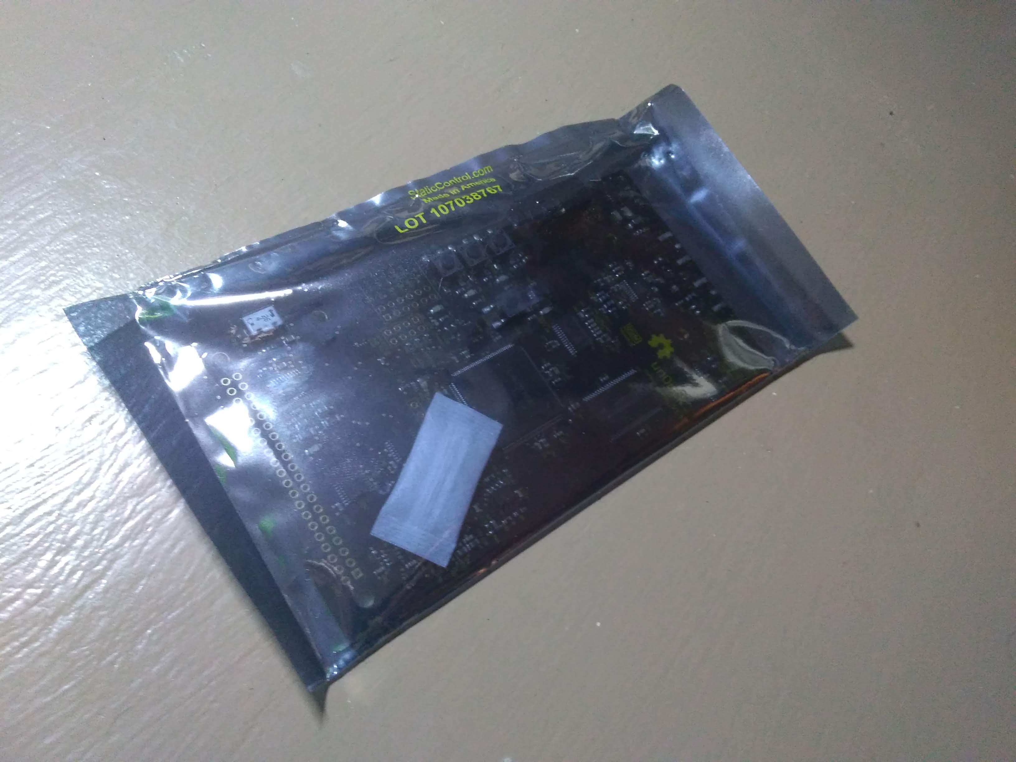
Board in a bag
What do we need ?
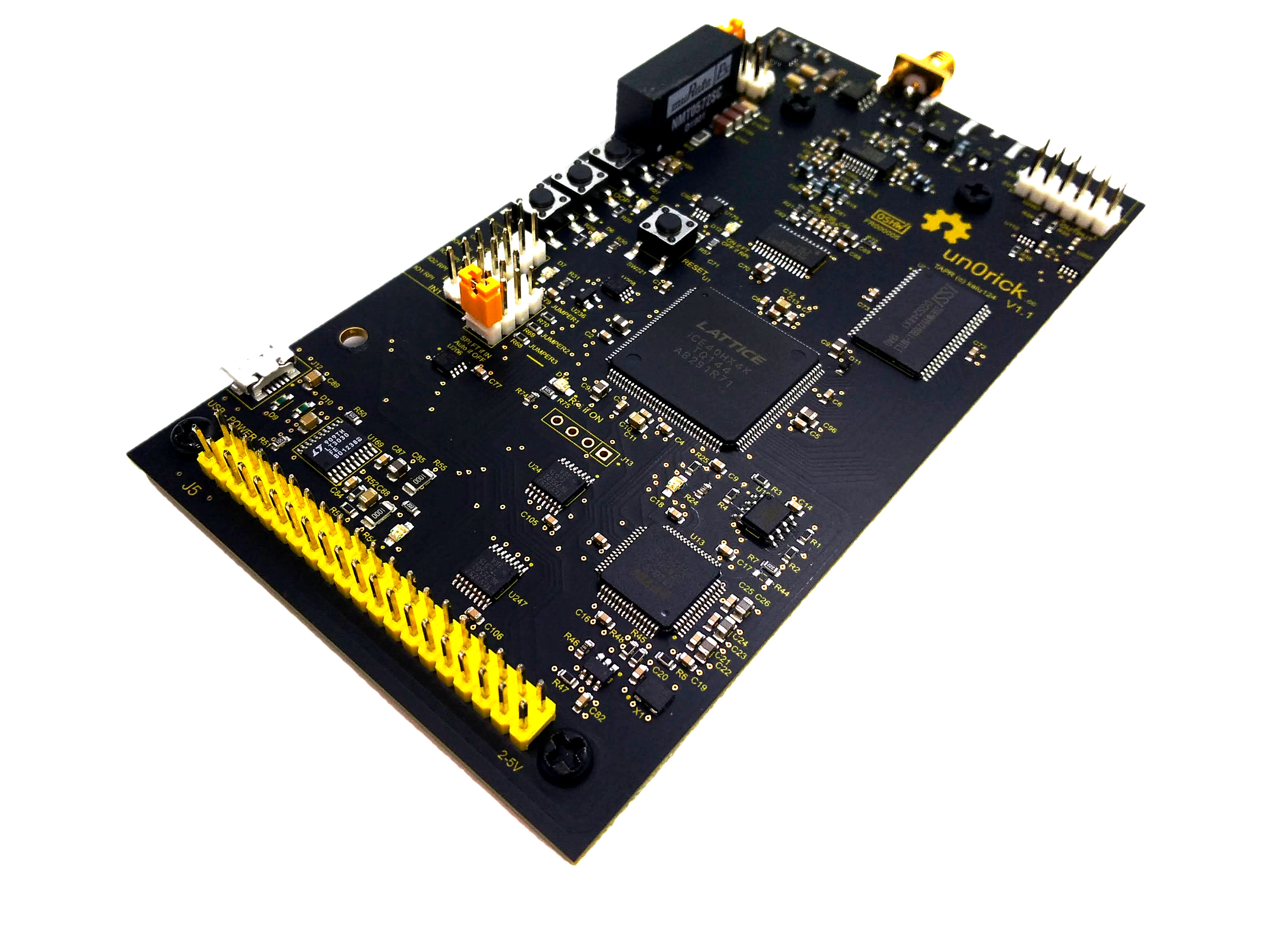
Assembled !

Software side
Updating the raspberry tools
You may need to install new packages, especially to communicate with the fpga.
sudo apt-get update
sudo apt-get install i2c-tools libasound2-dev python3-numpy python-numpy
sudo apt-get install python-dev libatlas-base-dev libportaudio2
From a general perspective, it may be worth trying to keep your tools up to date with:
sudo apt-get upgrade
If you face SPI / GPIOs issues, and that you are using a RPi4, you may want to follow these hints to update WiringPi. In short:
cd /tmp
wget https://project-downloads.drogon.net/wiringpi-latest.deb
sudo dpkg -i wiringpi-latest.deb
gpio -v
to check you’re using v2.52 or above.
Updating the python tools
On the raspberry pi, use pip to install the following modules:
pip3 install smbus2 RPi.GPIO PyAudio matplotlib numpy scipy spidev
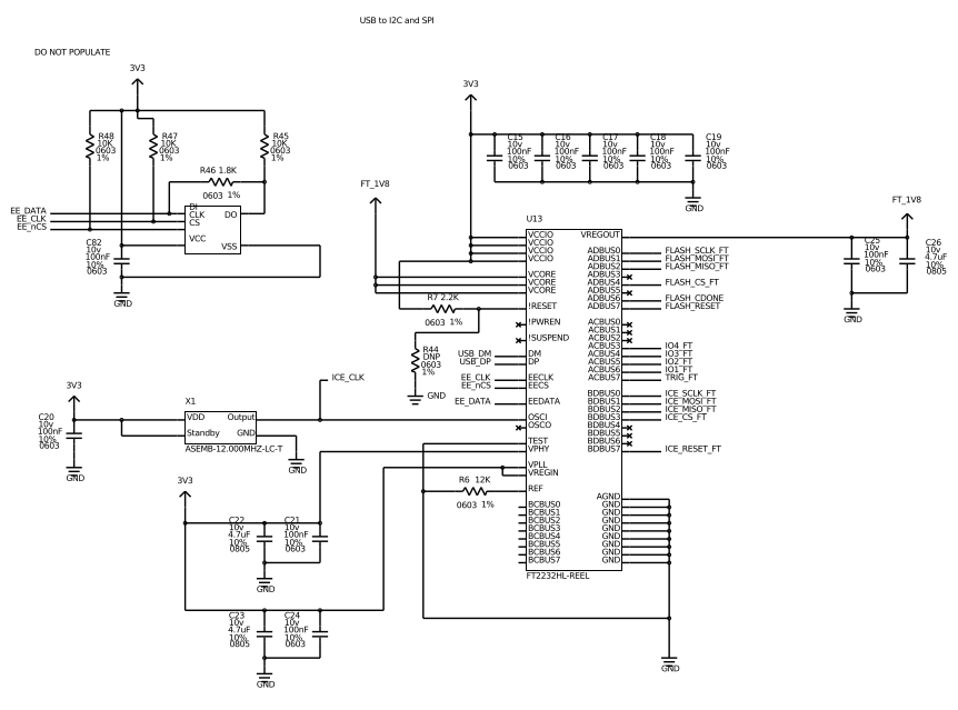
How to update the FPGA binary
- Use a PC with (for example) diamond programmer or (preferred ;) ) using iceprog.
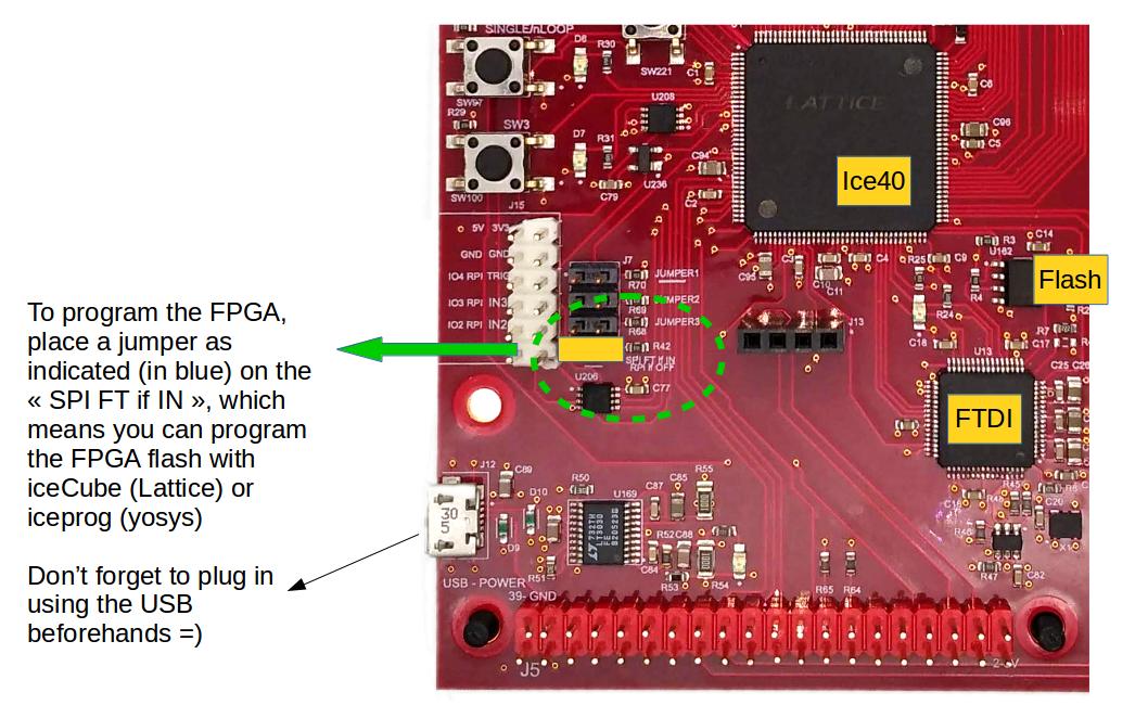
- Setup the the jumper for FPGA update (on J23, equivalent or Jumper4, named “SPI FT if IN”)
- Connect the USB
- Program via (for example) the diamong programmer application
- The LED program shall be lit when programmed successfully.
Installing iceprog to flash the fpga
iceprog is the software used to put the fpga on the flash storage on the board, which will be read by the fpga on boot. The easiest way is to :
sudo apt install fpga-icestorm
If this doesn’t work, then this may work:
sudo apt-get install libftdi-dev git gcc
git clone https://github.com/cliffordwolf/icestorm.git
cd iceprog
make
sudo make install
This will create and install the iceprog utility, used to flash the fpga program (bitstream).
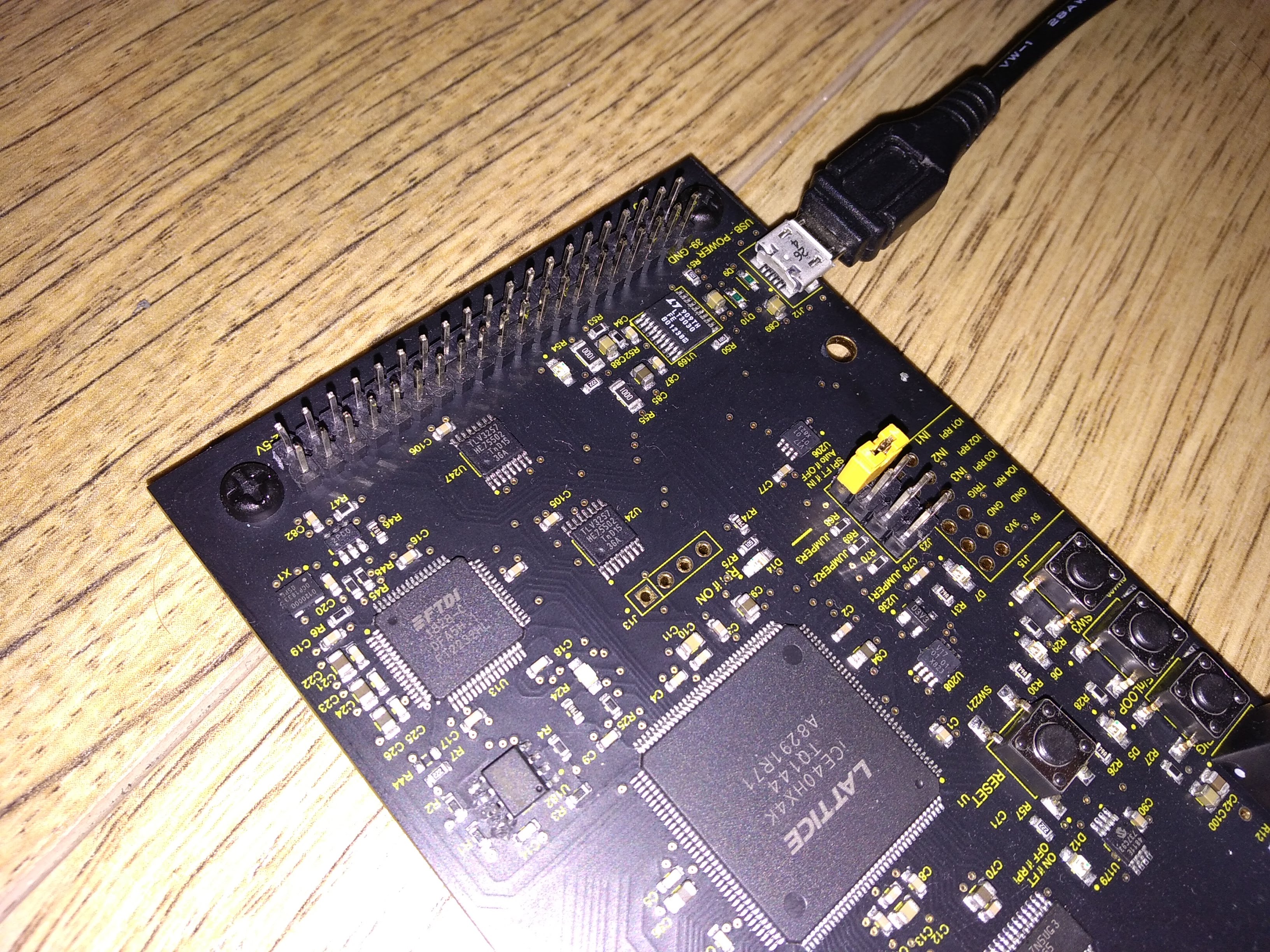
Prepare the jumper here :
Then, plug an usb cable from the RPi to the board (not connected using the raspberry pi header).
Check that the FTDI device is well created by typing:
dmesg
and then flash the FPGA by doing:
wget https://github.com/kelu124/un0rick/raw/master/bins/v1.1.bin
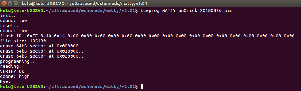
iceprog v1.1.bin
This should flash the board:
If you do not have a success here, you may want to have a look at how to connect FTDI devices to your computer (see for example: https://stackoverflow.com/questions/36633819/iceprog-cant-find-ice-ftdi-usb-device-linux-permission-issue ). Usually, one has no issues with RPi fresh out of the box.
Alternative for programming only using the RPi (no USB)
See https://github.com/kelu124/un0rick/tree/master/pyUn0/rpi for the files, and sources of scripts.
- Download this archive with
wget https://github.com/kelu124/un0rick/raw/master/pyUn0/rpi.zipand unzip it on the Pi. - Make sure the pi is connected to the board, and that the jumper located in this picture is removed.
- Compile the programmer by typing
Makein the shell - Check the size of your flash by typing
./creset.shfirst and thenflashrom -p linux_spi:dev=/dev/spidev0.1,spispeed=2048. It should yield the size of the flash. Edit thencreatepadded.sh, so thatcat v1.1.bin /dev/zero | dd bs=1024 count=2048 of=padded.binreplacing 2048 with the size of your flash in kB. Runcreatepadded.shto create a binary to flash your flash. - Program your board with
flashrom.sh - Put back the jumper from this picture.
- And voilà! You can use your board with the
pyUn0.pylib.
Physical setup / connections for the lib acquisitions
Pinouts
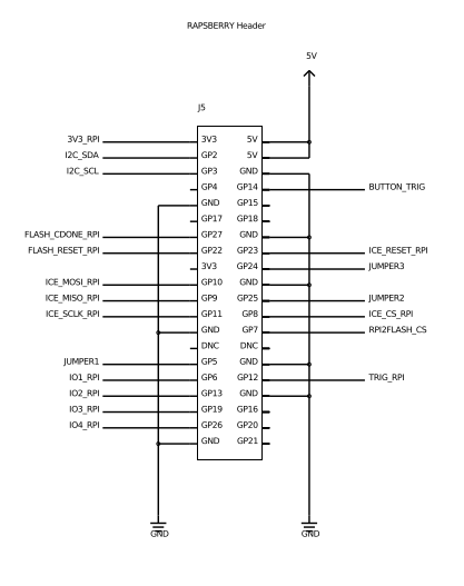
Raspberry Pi header
FTDI breakout
Setup
You can use a RPi4 with a ribbon cable to connect to the board, leaving the jumper on, putting one to select the high voltage level, connecting a piezo.. and that’s it.
Running an acquisition
Testing the connection to the board
Then, for example to discover the board using Python, you can use the library:
git clone https://github.com/kelu124/pyUn0-lib.git
cd pyUn0-lib
python pyUn0.py test
It will download the lib, then you should see with the ‘test’ option a LED blink
Testing the connection to the board
The “single” option will allow you to capture a single line, then the “process” one will create the corresponding images.
python pyUn0.py single
python pyUn0.py process
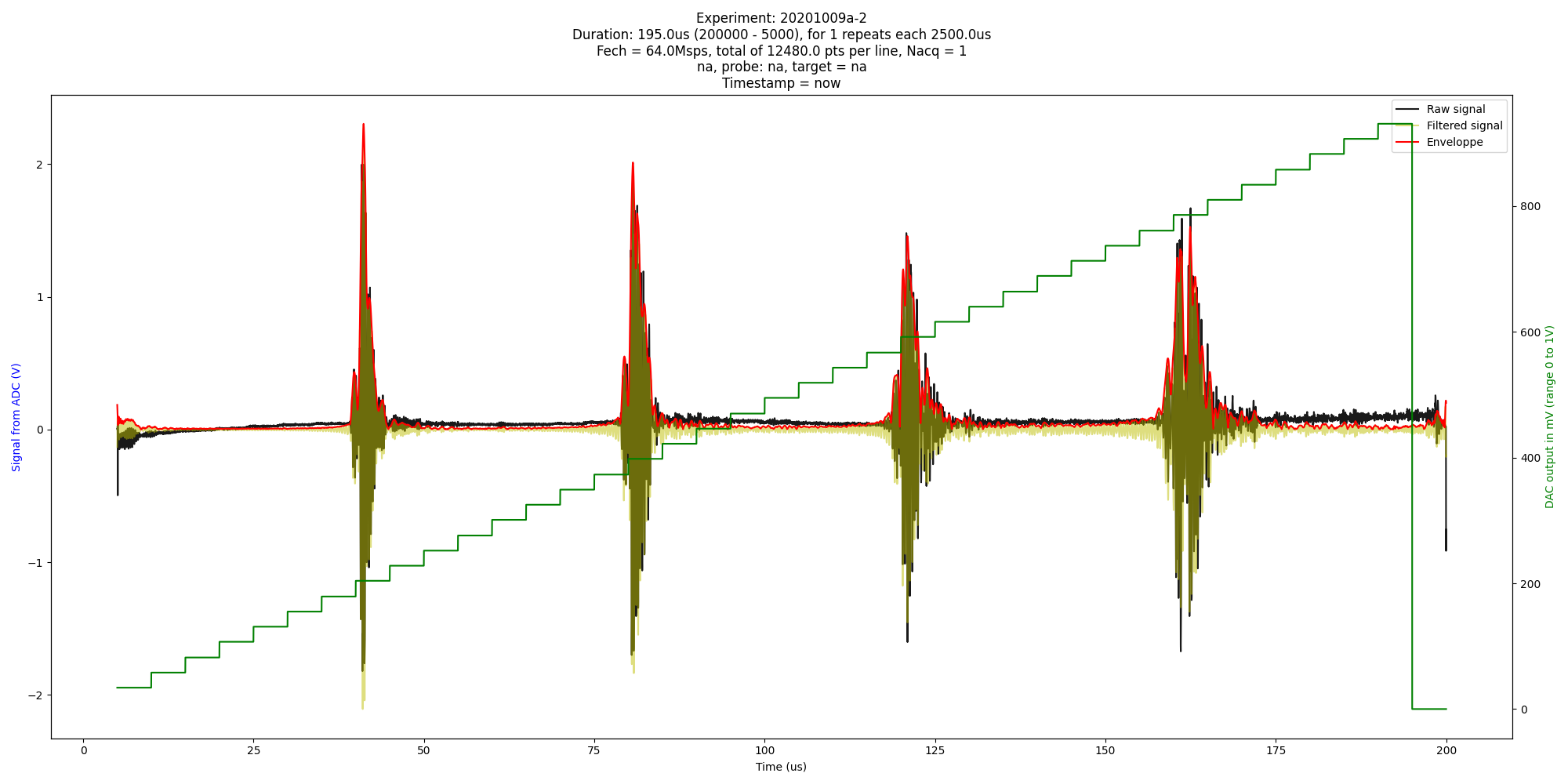
Results
I’ve used this exact setup to get the lib examples ( https://github.com/kelu124/pyUn0-lib ).
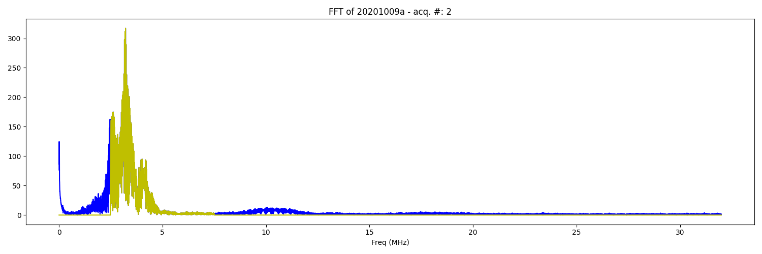
Example of an acq :
with a clean spectrum:
# Details of the RPi binary registers and specificities
Does not work with the USB binary!
You don’t need to read all of this, this is included in this version of the python lib.
FPGA setup
SPI is used to configure the DAC values every 5us, using the following addresses and protocol (SPI is only 8bits per CS). For each address:
- Send 0xAA to access parameters
- Followed by Send @ the address over 8 bits
- Followed by Send Data, a parameter over 8 bits
Addresses start at 0xE0 and end at 0xD0 on the default bitstream.
Details of adresses to setup the board
| Address | Name of variable | Size (bits) | Description | Default value in hex | unit | Value |
|---|---|---|---|---|---|---|
| 0xE0 | sEEPon | 8 | Lengh of Pon | 0x14 | 10ns | 200 ns |
| 0xD0 | sEEPonPoff | 8 | Lengh between Pon and Poff | 0x0A | 10ns | 100 ns |
| 0xE1 | sEEPoff | 8 | Lengh of Poff MSB | |||
| 0xE2 | sEEPoff | 8 | Lengh of Poff LSB | 0xC8 | 10ns | 2000 ns |
| 0xE3 | sEEDelayACQ | 8 | Lengh of Delay between Poff and Acq MSB | 0x02BC | 10ns | 7000 ns |
| 0xE4 | sEEDelayACQ | 8 | Lengh of Delay between Poff and Acq LSB | |||
| 0xE5 | sEEACQ | 8 | Lengh of acquisition MSB | 0x32C8 | 10ns | 130 us |
| 0xE6 | sEEACQ | 8 | Lengh of acquisition LSB | |||
| 0xE7 | sEEPeriod | 8 | Period of one cycle MSB | 0x186A0 | 10ns | 1 ms |
| 0xE8 | sEEPeriod | 8 | Period of one cycle 15 to 8 | |||
| 0xE9 | sEEPeriod | 8 | Period of one cycle LSB | |||
| 0xEA | sEETrigInternal | 1 | Software Trig : Auto clear | 0 | N/A | |
| 0xEB | sEESingleCont | 1 | 0: single mode 1 continious mode | 0 | N/A | |
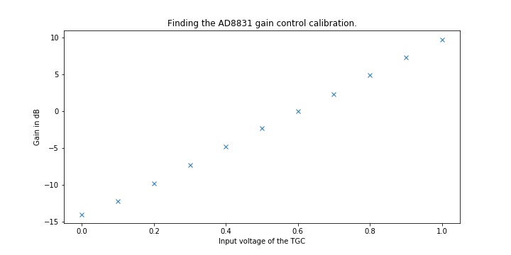
| 0xEC | sEEDAC | 8 | Voltage gain control: 0V to 1V | 0x11 | 0,004 | 68 mV |
| 0xED | sEEADC_freq | 8 | Frequency of ADC acquisition | 0x03 | 64/(1+f) MHz | 16 MHz |
| 0xEE | sEETrigCounter | 8 | How many cycles in countinious mode | 0x0A | cycles | 10 cycles |
| 0xEF | sEEpointerReset | 1 | Sofware memory reset: set to 1; auto clear | 0 |
How to read from the FPGA
SPI is used to read the ADC value. SPI in the case of the basic program is only 8 bits per CS.
Master send 0. If the FPGA is doing an acquisition, the returned value is 0xAA, else the value is on 2x8 bits.
- MSB
- 8th bit: MSB ID: set to 1
- 6-7th bit: cycle bits: to identify a line in a sequence
- 4-5th bits: the two inputs (TopTurn 1 and TopTurn2) in case a counter is used.
- 1st-3th bits: ADC 7 to 9: 3 remaining bits of acquisition
- LSB
- 8th bit: LSB ID: set to 0
- 1st to 7th bits: ADC 7-0: 7 first bits of acquisition
If the master reads more data than the board has acquired, SPI will return old or incorrect values: the master has to know how many measures were done.
DAC Configuration
SPI is used to configure the DAC values every 5us, using the following addresses and protocol (SPI is only 8bits per CS). For each register setup, you will have to send:
- Send 0xAA to tell the board you’ll be setting a register
- Followed by Send @ the address over 8 bits
- Followed by Send Data, a parameter over 8 bits
Addresses start at 0x10 and end at 0x38. This corresponds to t = 0us for 0x10, and t = 200us for 0x38. Data range from 0 to 8 bits for full amplification.
TGC use
The gain was measured to check if it was working and yielded this gain curve according to the value put into the DAC.