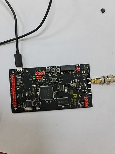
How to setup the board using only a usb cable
Beware! If you use this, you just need to have a usb cable plugged in.
Install jumpers and connectors as indicated in the figure below. Jumpers necessary are the white and the green ones.
Installation
Preparing Python
pip3 install pyftdi matplotlib numpy scipy
Installing iceprog to flash the fpga
iceprog is the software used to put the fpga on the flash storage on the board, which will be read by the fpga on boot. The easiest way is to :
sudo apt install fpga-icestorm
If this doesn’t work, then this may work:
sudo apt-get install libftdi-dev git gcc
git clone https://github.com/cliffordwolf/icestorm.git
cd iceprog
make
sudo make install
This will create and install the iceprog utility, used to flash the fpga program (bitstream).
FTDI rules.
Notes for Linux: Create a file /etc/udev/rules.d/53-lattice-ftdi.rules with the following line in it to allow uploading bit-streams as unprivileged user:
ATTRS{idVendor}=="0403", ATTRS{idProduct}=="6014", MODE="0660", GROUP="plugdev", TAG+="uaccess"
This should solve usb access rules.
Setting jumpers
Put jumpers on the J23 header, only on Jumper2 and on "SPI FT if ON". See at the bottom of the page for the VGA connections.
Optional: connection for VGA
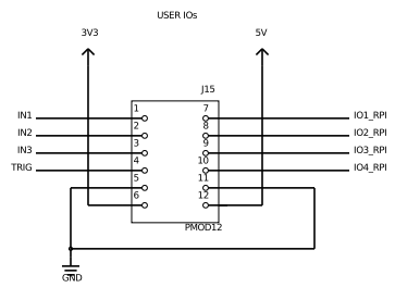
For this binary, you will need to connect VGA lines to the board, using the header close to the buttons (beware, this image should be rotated to align with the actual board silkscreen).
- IO1_RPI = GREEN (color of your choice really)
- A 270 Ohm R should be inserted in series with the line.
- IO2_RPI = VSYNC
- A 120 Ohm R should be inserted in series with the line.
- IO4_RPI = HSYNC
- A 120 Ohm R should be inserted in series with the line.
- GND = GND
Beware, IO3 seems not to be working on this bin.
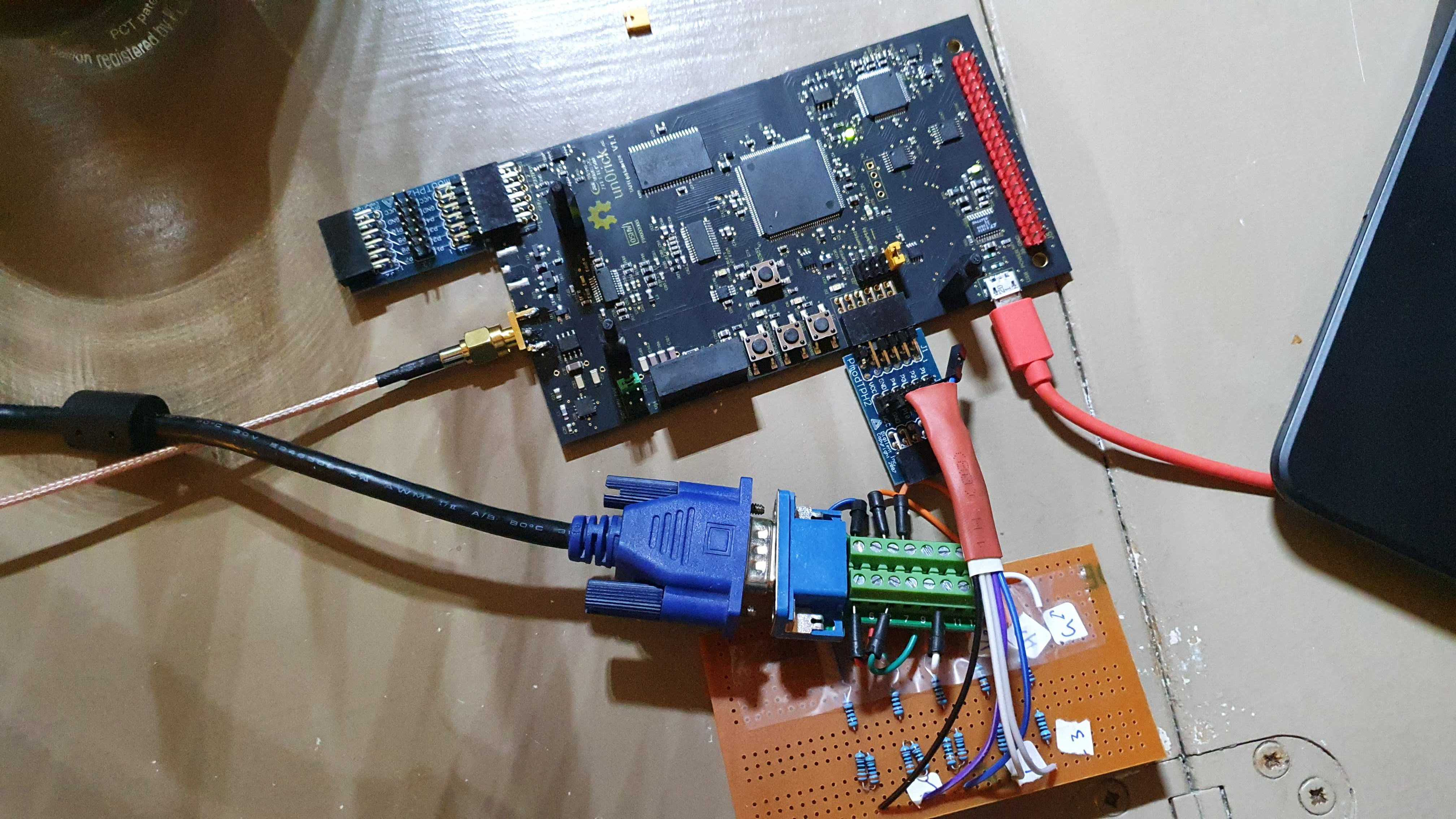
Below, and example of my connections with nice resistors.
Connect the usb cable
Check that the FTDI device is well created by typing:
dmesg
Programming it
wget https://github.com/kelu124/un0rick/raw/master/usb/usb.bin
iceprog usb.bin
Using the python lib
In python
In essence, installing the module pip3 install un0usb before, or, to get a specific one:
wget https://github.com/kelu124/un0rick/raw/master/usb/python_lib/un0usb-0.2.6.tar.gz
pip3 install un0usb-0.2.6.tar.gz
Then, from a python shell, you can initialise the board with the following code.
import un0usb as USB # neeeds `pip3 install un0usb` before
fpga = USB.FpgaControl('ftdi://ftdi:2232:/', spi_freq=8E6) # init FTDI device
fpga.reload() # reload configuration
fpga.reset() # reset fpga

file = fpga.stdNDTacq() # Running a standard NDT acquisition
plot = USB.FView() # Opens a viewing object
data = plot.readfile(file) # plots it
After the fpga.reset() command, D7 should be starting to blink.
Managing the VGA output
If not jumper is put on Jumper2, you should start having on the VGA output a picture of what is happening on the board in real time. The board registers and parameters can be set via USB, but acquisition triggers is managed by the board itself, not allowing you to read from the buffer.
If a jumper is set on Jumper2, the display with only display the latest acquisition, and the board will be fully controlable via USB, including the option to read from the board RAM.
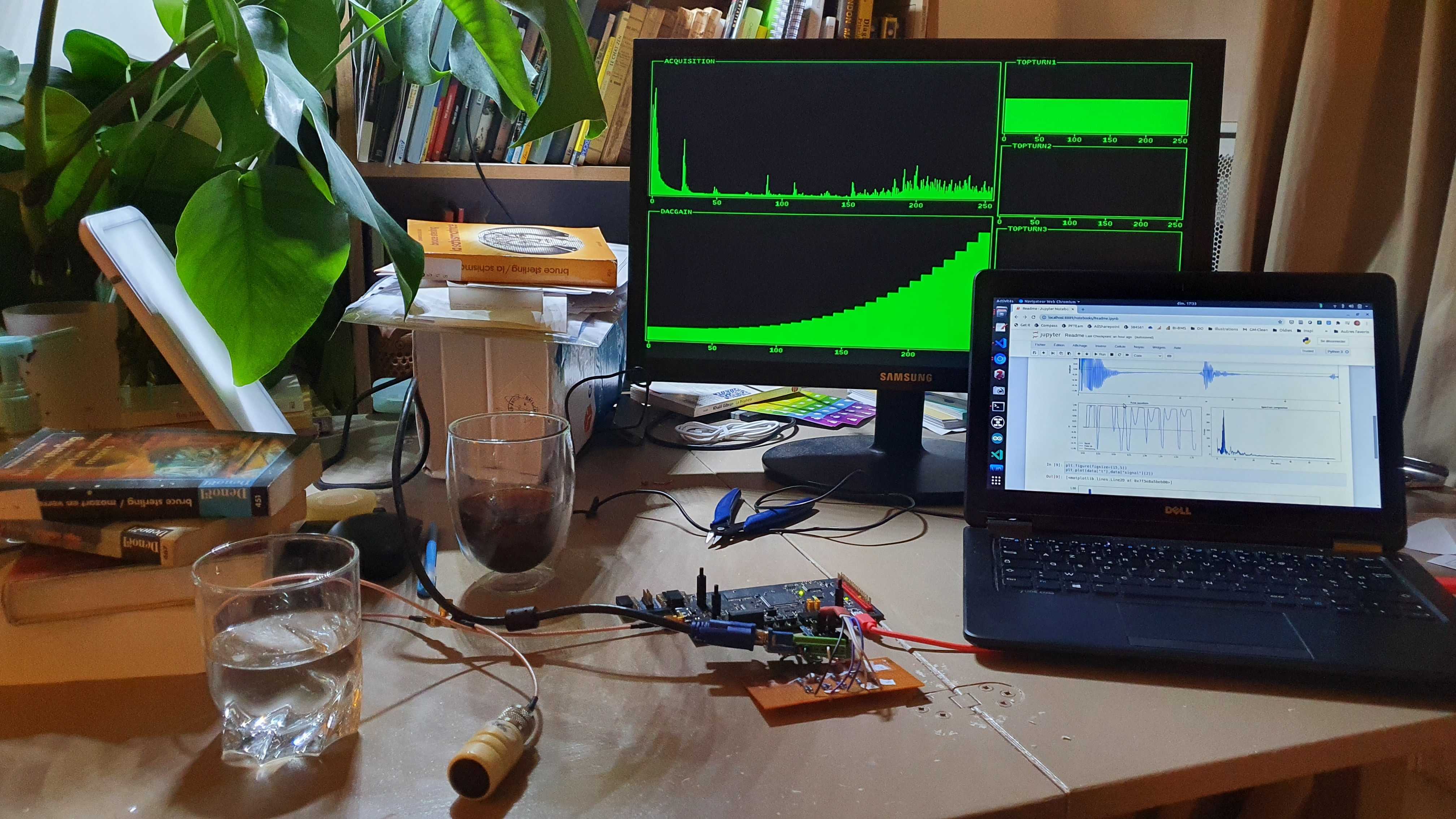
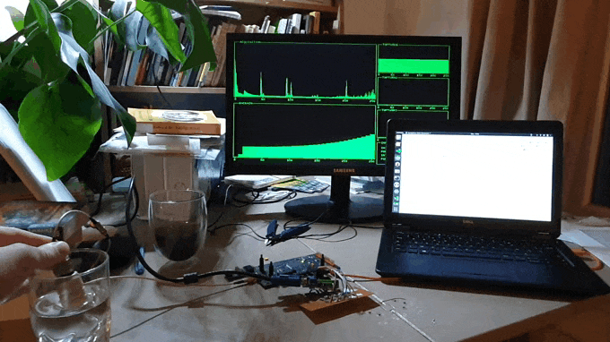
Result
The full log is here.
Going in deeper details
###
The lib and examples should be self sufficient. However, you can go at a deeper level by exploring the un0usb library.
Pulser control
To control the waveform, one would set the fpga.csr.ponw, fpga.csr.interw and fpga.csr.poffw, that are respectively integers for setting the width (timing) of the pulse, width of a relaxation period before damping, and then duration of damping. Unit are (1/128us).
The fpga.csr.initdel register is the delay between the beginning of the acquisiton and the pulse.
fpga.csr.initdel = InitDel
fpga.csr.ponw = PONWidth
fpga.csr.interw = INTERWidth
fpga.csr.poffw = PDAMP
Below is plotted amplitude of an echo as a function of the fpga.csr.ponw for a 4MHz transducer. One sees that a setting at 16 provides most
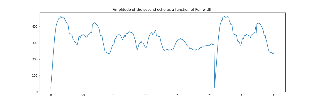
(See full experiment here).
Gain and acquisitions
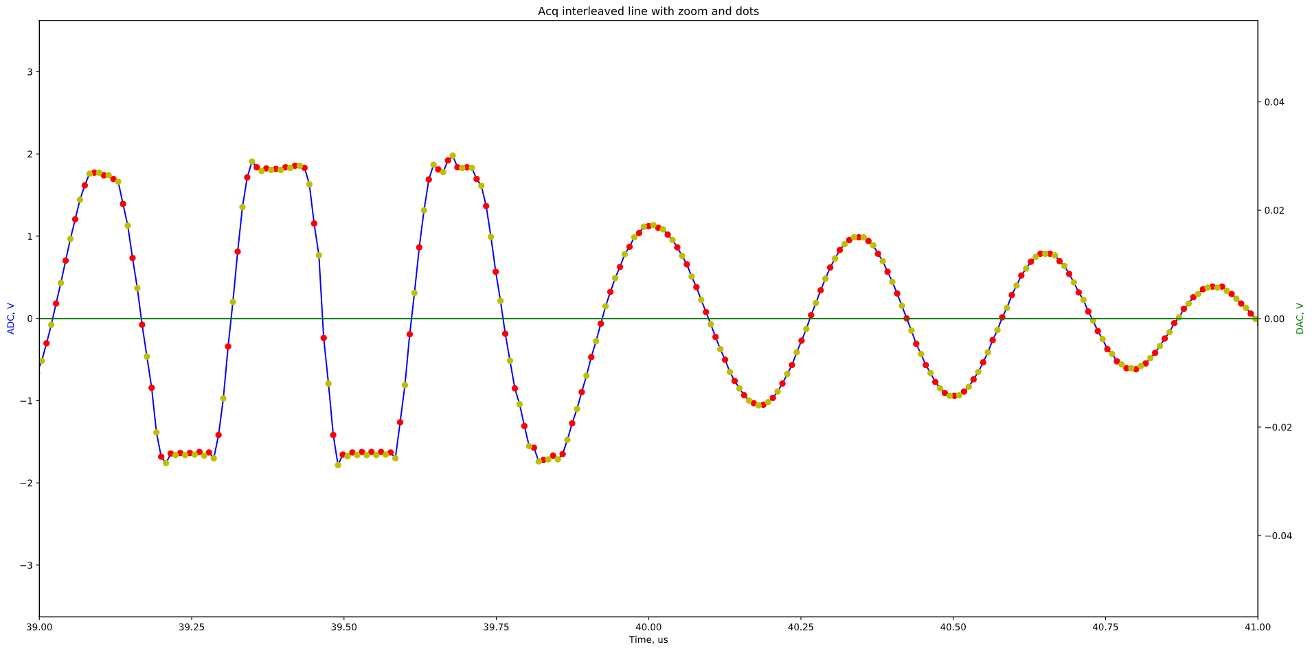
And do acquisitions with acq_res = fpga.do_acquisition(acq_lines=32, gain=gain, double_rate=True) which will return an array of acq_lines acquisitions, of length 256us at 64Msps. double_rate=True provides a half clock offset to odd lines, so that one can interleave two subsequent acquisition to have, in a fixed setting, a 128Msps acquisition.
The gain setting is an array of integers, of length 32, that can range from 0 to 1023, controlling gain for each of the 32 8us-segment of acquisition within the 256us line.
Other registers
fpga.csr.led3 = 0sets LED3 off. led1, led2, led3 are possible, can be set to 0 or 1.fpga.csr.topturnXreads input 1 to 3 on the input header.fpga.csr.jumperXreads jumper 1 to 3 close to the programming jumper.fpga.csr.outXicewrites/reads output 1 to 3.fpga.csr.nblines = acq_lines - 1is the register controlling the number of lines acquired.fpga.csr.dacoutreads the DAC/TGC/VGA level outside of acquisitions.fpga.csr.acqstart = 1to start the acquisitionfpga.csr.drmode = int(double_rate)triggers the interleaving mode.fpga.csr.acqstart = 1to start the acquisitionfpga.csr.acqdoneis equal to 0 during acquisitions.fpga.csr.authorreads the ID of the author of the binary.1: kelu124
fpga.csr.versionreads the ID of the author’s binary.1The current binary version
Don’t hesitate to improve the gateware and push more here.
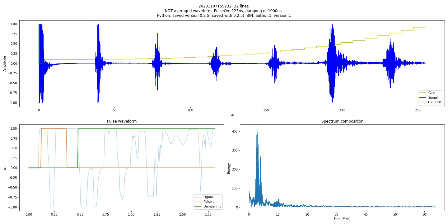
Example of acquisitions
Raw signal, with DAC
The signal is in blue, the gain levels are in green. Here there are 32 visible steps, of 8us each. 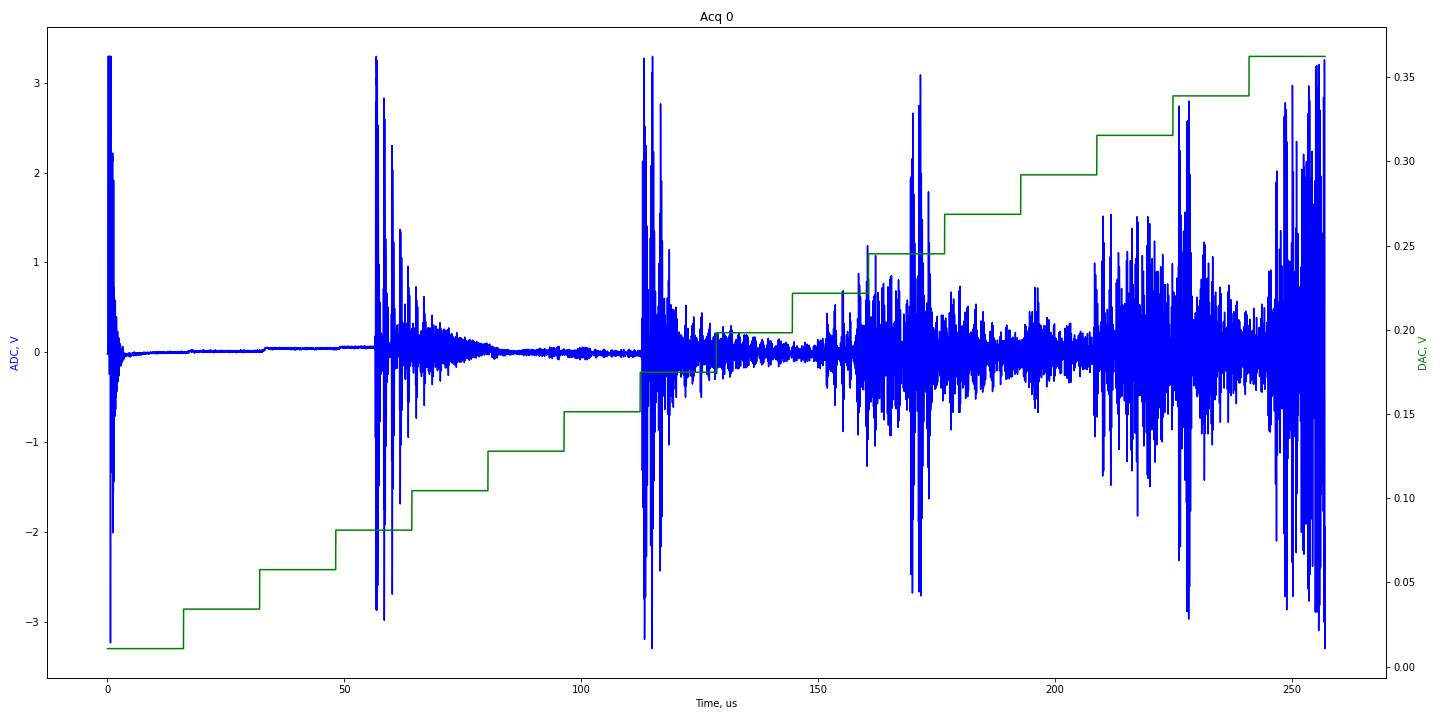
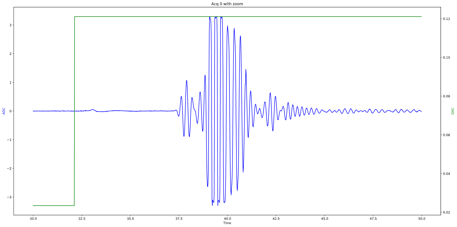
Detail of an echo
Interleaved acquisiton mode = ON
Doublign acquisition speed (yellow and red dots below)