Setup
The un0rick board was set up to connect with the m5stack
/* CONNECTIONS BETWEEN RPi and m5stack
  M5STACK pin22 -> RPi header GPIO 23 (Ice40 reset)
  M5STACK pin21 -> RPi header GPIO 8 (Ice40 CS)
  M5STACK pin19 -> RPi header GPIO 10 (Rpi MISO)
  M5STACK pin23 -> RPi header GPIO 9 (Rpi MOSI)
  M5STACK pin18 -> RPi header GPIO 11 (Rpi  CLK)
  M5STACK GND to RaspberryPi header GND pin
  M5STACK 5V ->  RaspberryPi header 5V pin
*/
The overall setup for this experiment was as follows:
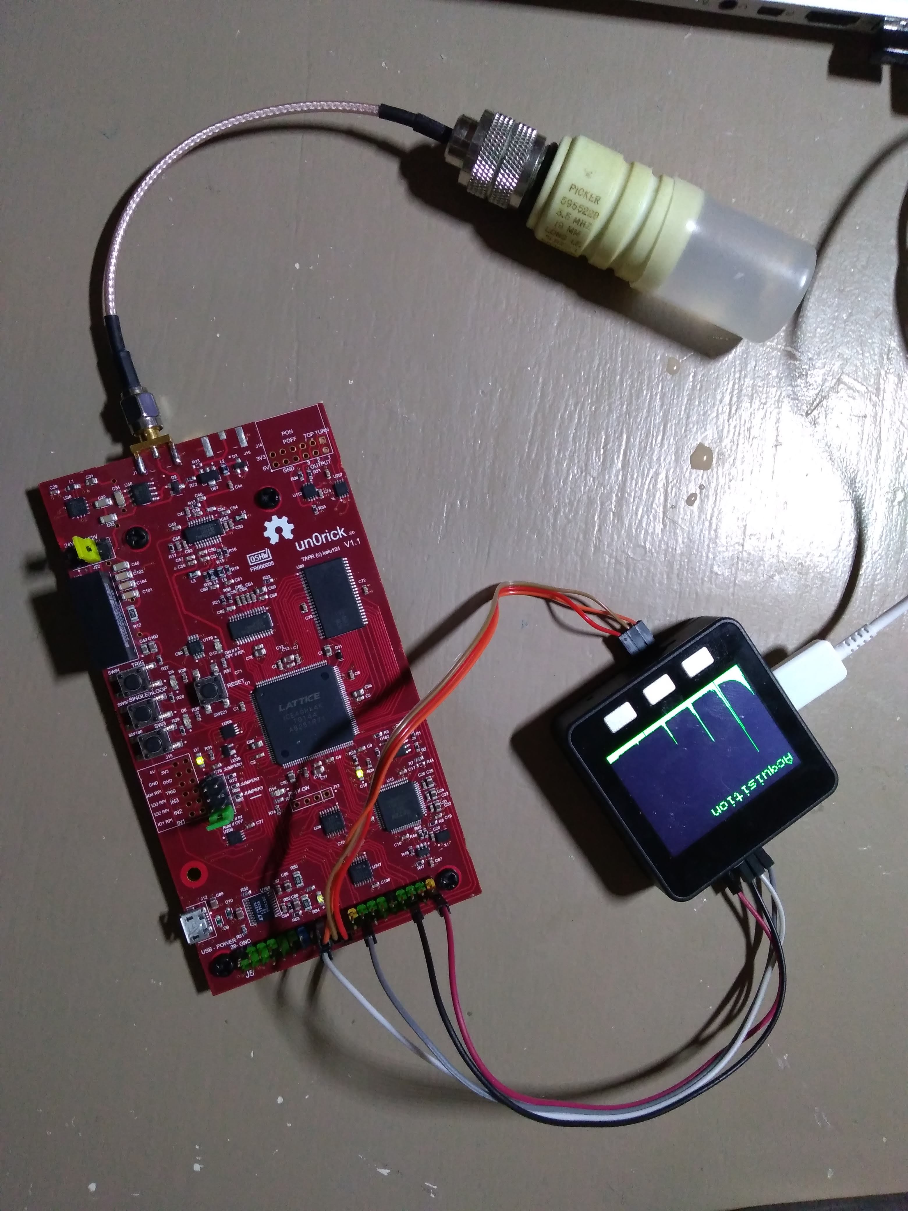
and yielded the following results

One will see the echoes from the bottom of the mug appearing.

Code
The following code was used on the m5stack.
#include <SPI.h>
#include <M5Stack.h>

/* CONNECTIONS BETWEEN RPi and m5stack
  M5STACK pin22 -> RPi header GPIO 23 (Ice40 reset)
  M5STACK pin21 -> RPi header GPIO 8 (Ice40 CS)
  M5STACK pin19 -> RPi header GPIO 10 (Rpi MISO)
  M5STACK pin23 -> RPi header GPIO 9 (Rpi MOSI)
  M5STACK pin18 -> RPi header GPIO 11 (Rpi  CLK)
  M5STACK GND to RaspberryPi header GND pin
  M5STACK 5V ->  RaspberryPi header 5V pin
*/

#define ICE40RESET 22
#define ICE40CS    21
#define ICE40MISO  19
#define ICE40MOSI  23
#define ICE40CLK   18
#define PTS        3200
#define LenAcq      2*PTS+1
#define LenData      PTS+1

// Sound aspects
#define D0 -1 //silence
//THE FIRST OCTAVE
#define B1 262 //Do (B)
#define D1 294 //Re (D)
#define E1 330 //Mi (E)

uint16_t MaxPt = PTS / 2;
int CenterPeak = 80;
uint16_t DATA[LenAcq];
uint16_t RAWDATA[LenData];

uint16_t CLEANDATA[320];
int Factor = 80;
int SPIMODE = 1;
int i = 0;
int j = 0;
int value = 0;

int GainLevel = 400;
bool MSBF = true;

void SetGain(  ) {
  for (int i = 0; i <= 40; i++) {
    WriteFPGA(16 + i, 400 / 4);
  }
}

void buttons_test() {
  int MAXARRAY = 0;

  if (M5.BtnA.wasPressed()) {

    M5.Lcd.fillScreen(BLACK);
    M5.Lcd.setCursor(10, 10);
    M5.Lcd.setTextColor(TFT_RED);
    M5.Lcd.setTextSize(3);
    M5.Lcd.printf("Testing if connection is OK \n\n");

    M5.Lcd.printf("LED 2 should be blinking 3 times \n\n");
    TestFPGA();
    TestFPGA();
    TestFPGA();


    M5.Speaker.tone(B1, 200); //frequency 3000, with a duration of 200ms

  }

  if (M5.BtnB.wasPressed()) {
    M5.Lcd.fillScreen(BLACK);
    M5.Lcd.setCursor(10, 10);
    M5.Lcd.setTextColor(TFT_RED);
    M5.Lcd.setTextSize(3);
    M5.Lcd.printf("Details of a peak\n\n");

    CenterPeak = MaxPt * Factor;
    for (int i = 0; i <= 319 / 2; i++) {

      M5.Lcd.drawPixel(2 * i, RAWDATA[CenterPeak - 320 / 4 + i] / 4 + 20, TFT_RED);

      M5.Lcd.drawLine(2 * i, RAWDATA[CenterPeak - 320 / 4 + i] / 4 + 20, 2 * i + 2, RAWDATA[CenterPeak - 320 / 4 + i + 1] / 4 + 20, TFT_ORANGE);

      /*if (i < 5) {
        M5.Lcd.printf("%3d ; ", i);
        M5.Lcd.printf("%3d \n", RAWDATA[CenterPeak - 320 / 2 + i] / 4);
        }
      */
    }

    M5.Speaker.tone(D1, 200); //frequency 3000, with a duration of 200ms

  }

  if (M5.BtnC.wasPressed()) {
    M5.Lcd.fillScreen(BLACK);
    M5.Lcd.setCursor(10, 10);
    M5.Lcd.setTextColor(TFT_GREEN);
    M5.Lcd.setTextSize(3);
    M5.Lcd.printf("Acquisition\n\n");
    // Read
    WriteFPGA(0xEF, 0x01); // cleaning pointer
    WriteFPGA(0xEA, 0x01); // trigging acquisition
    delay(200);
    GetData();


    /*
        for (int i = 0; i <= 20; i++) {
      M5.Lcd.printf("%3d -- ", DATA[2 * i]);
      M5.Lcd.printf("%3d -->  ", DATA[2 * i + 1]);
      M5.Lcd.printf("%3d\n", RAWDATA[i]);
      }
    */
    Factor = PTS / 320; // PTS = 3200 pts (16msps * 200us)
    for (int i = 0; i <= 319; i++) {
      value = 0;
      for (int j = 0; j <= Factor ; j++) {
        value = value + abs(RAWDATA[i * Factor + j] - 512);
      }
      if (value >  MAXARRAY ) {
        if  (i < 310) {
          MAXARRAY = value;
          MaxPt = i;
        }
      }
      value = value / (Factor * 2); // 240 (512, going into 240)
      M5.Lcd.drawFastVLine(i, (240 - value) - 10, 240 - 10, TFT_GREEN);
    }
    M5.Lcd.drawRect(230, 0, 240, 320, BLACK);
    //M5.Lcd.printf("== Value Max at %3d \n", MaxPt);

    //M5.Lcd.drawFastVLine(0, 0, 100, TFT_RED);
    //M5.Lcd.drawFastVLine(319, 0, 200, TFT_GREEN);

    M5.Speaker.tone(E1, 200); //frequency 3000, with a duration of 200ms

  }
}


void SetupFPGA() {
  GainLevel = 200;
  SetGain(); // TGC level

  // Duration of Pon
  WriteFPGA(0xE0, 0x19 ); // 200ns Pon
  // Duration between Pon and Poff
  WriteFPGA(0xD0, 0xC ); // 12*7.8125ns delay between Pon and Poff
  // Duration of damper
  WriteFPGA(0xE1, 0 ); //
  WriteFPGA(0xE2, 254 ); //
  // Duration betwen beginning and end of acquisition
  WriteFPGA(0xE3, 2 ); //
  WriteFPGA(0xE4, 128 ); //
  // Length of acquisition
  WriteFPGA(0xE5, 0x60 ); //
  WriteFPGA(0xE6, 0x00 ); // 0x60 * 255 *   7.8125ns duree
  //Freq
  WriteFPGA(0xED, 3); // setting freq as 64Msps / (1+arg) eg 3 = 16msps
  //Shoot
  WriteFPGA(0xEB, 0x00); // Doing 1 shot
}


void GetData() {


  for (int i = 0; i <= LenAcq; i++) {
    DATA[i] = 0;
  }

  for (int i = 0; i <= LenData; i++) {
    RAWDATA[i] = 0;
  }

  for (int i = 0; i <= LenAcq; i++) {
    SPI.beginTransaction(SPISettings(1000000, MSBFIRST, SPI_MODE0));
    digitalWrite(ICE40CS, LOW);
    DATA[i] = SPI.transfer(0x00);
    digitalWrite(ICE40CS, HIGH);
    SPI.endTransaction();
  }

  for (int i = 0; i <= LenData ; i++) {

    RAWDATA[i] = 128 * (DATA[2 * i + 1] & 0b111) + DATA[2 * i + 2];

    /*
      if (i < 10) {
      M5.Lcd.printf("%3d ", DATA[2 * i + 1]); M5.Lcd.printf("%3d - ", DATA[2 * i + 1] & 0b111);
      M5.Lcd.printf("%3d ", DATA[2 * i ]); M5.Lcd.printf("%3d - ", DATA[2 * i + 2]);
      M5.Lcd.printf("%3d \n", RAWDATA[i]);
      }
    */
  }


}


void setup() {
  // put your setup code here, to run once:
  pinMode(ICE40CS, OUTPUT);
  pinMode(ICE40RESET, OUTPUT);


  // initialize SPI:
  //SPI.begin();


  SPI.beginTransaction(SPISettings(1000000, MSBFIRST, SPI_MODE0));
  SPI.endTransaction();

  Serial.begin(115200);         // SERIAL
  M5.begin();                   // M5STACK INITIALIZE
  M5.Lcd.setBrightness(200);    // BRIGHTNESS = MAX 255
  M5.Lcd.fillScreen(BLACK);     // CLEAR SCREEN
  M5.Lcd.setRotation(0);        // SCREEN ROTATION = 0

  M5.Lcd.setTextColor(TFT_RED);
  M5.Lcd.setTextSize(3);


  M5.Lcd.printf("Initialisation\n\n");
  delay(500);
  digitalWrite(ICE40RESET, LOW);
  delay(500);
  digitalWrite(ICE40RESET, HIGH);
  M5.Lcd.setTextColor(TFT_YELLOW);
  M5.Lcd.printf("RESET DONE\n\n");
  delay(500);
  M5.Lcd.setTextColor(TFT_GREEN);
  SetupFPGA();
  M5.Lcd.printf("FPGA has been set up for acquisitions\n\n");

}

int WriteFPGA(int address, int value) {

  //SPI.begin();
  SPI.beginTransaction(SPISettings(1000000, MSBFIRST, SPI_MODE0));

  digitalWrite(ICE40CS, LOW);
  SPI.transfer(0xAA);
  digitalWrite(ICE40CS, HIGH);
  delayMicroseconds(5);
  digitalWrite(ICE40CS, LOW);
  SPI.transfer(address);
  digitalWrite(ICE40CS, HIGH);
  delayMicroseconds(5);
  digitalWrite(ICE40CS, LOW);
  SPI.transfer(value);
  digitalWrite(ICE40CS, HIGH);
  delayMicroseconds(5);
  //SPI.end();
  SPI.endTransaction();
  return 1;
}

int TestFPGA() {
  M5.Lcd.printf("Blink 1 -  ");
  WriteFPGA(0xEB, 0x01);
  delay(750);
  WriteFPGA(0xEB, 0x00);
  delay(750);

}


void loop() {
  // put your main code here, to run repeatedly:
  //TestFPGA();

  buttons_test();
  M5.update();
}