BEWARE: This project has been deprecated since the arrival of the pic0rick project in 2024
un0rick
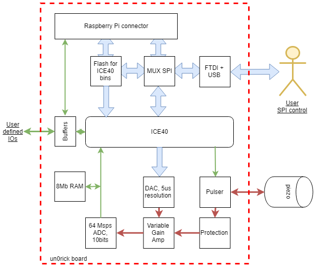
Overview
This is a simple single-channel ultrasound board. Block diagram below:
Step-by-step
- Program the fpga using a open-source toolchain to synthetise the embedded firmware.
- Control the board fully through SPI, be it through USB, a Raspberry Pi, or even an arduino (though a cheap one may not have sufficient resources to do what you want do to).
- Set up the acquisition sequence
- Get the data back again
- Process / visualize the acquistion
I recommend using RPi, particularly W for the wireless aspects, which then becomes the board server. There’s a dedicated 20x2 header. Prepared is a python lib as well. The v1.0.0 version is RPi4 proofed.
Two control options: usb or raspberry
Examples
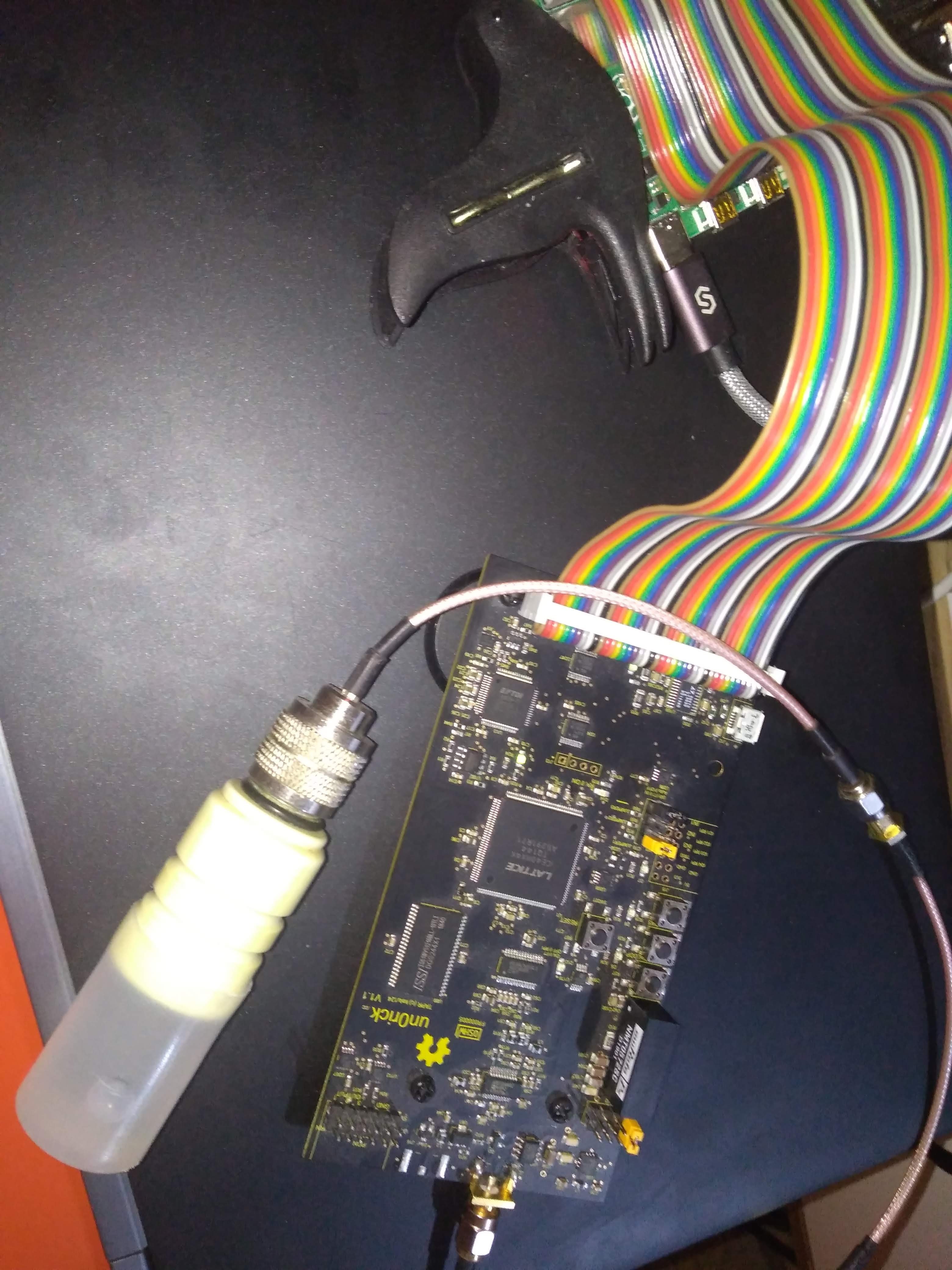
- With a Raspberry pi
The board was connected to a single element piezo, in water, with a reflector a few centimers away, immersed in water. Pulser is set up at 25V high pulses. Control was done through a Raspberry Pi W which is used as a controler and server, another Rasbperry pi.
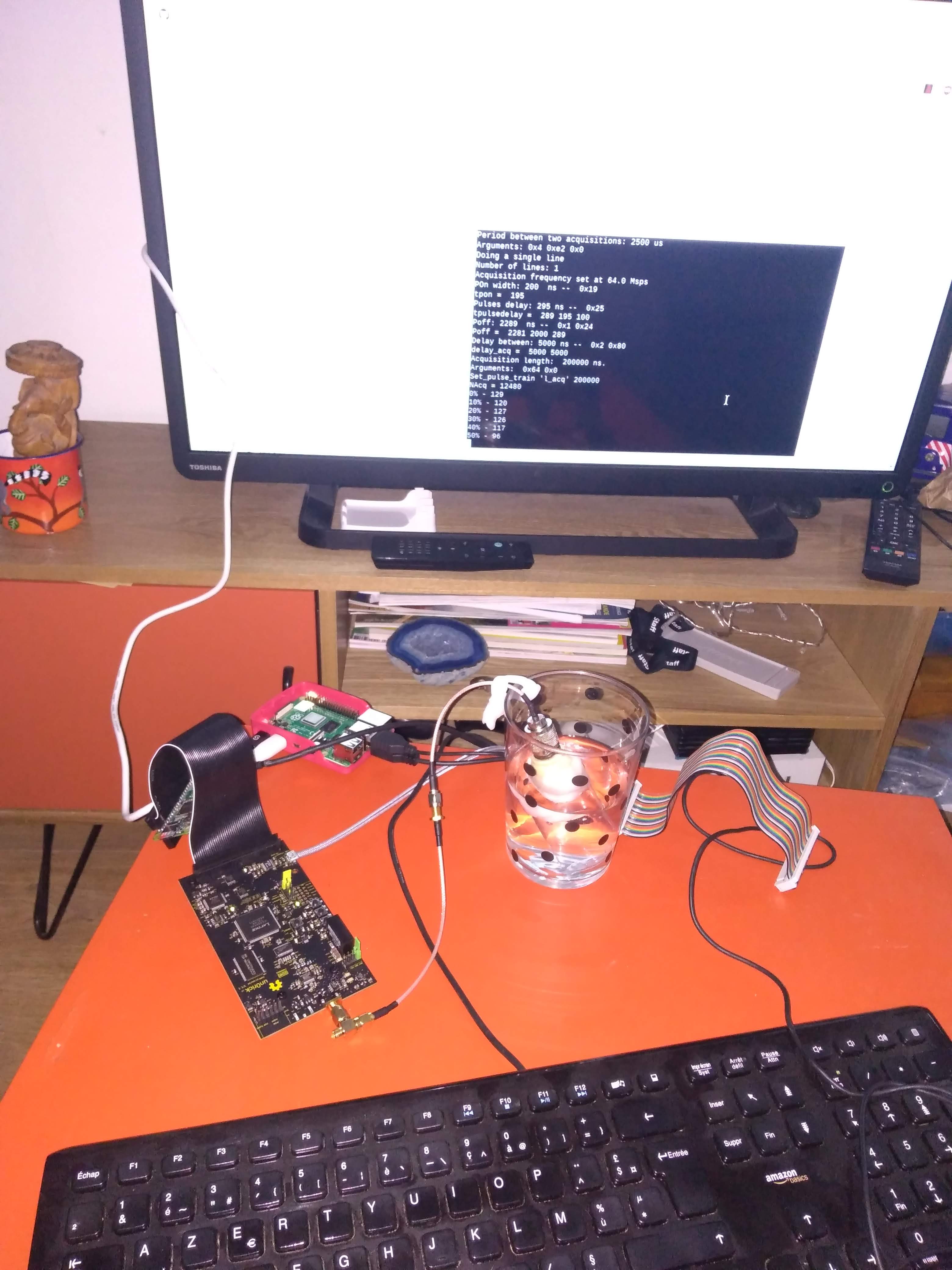
Acquisition is realized, with a small offset, between 32Msps and 64Msps. Data is explored a bit further.
- With a M5Stack (or any microcontroller really)
The board was also tested with a nice m5stack board (ino file). Below an example in image:
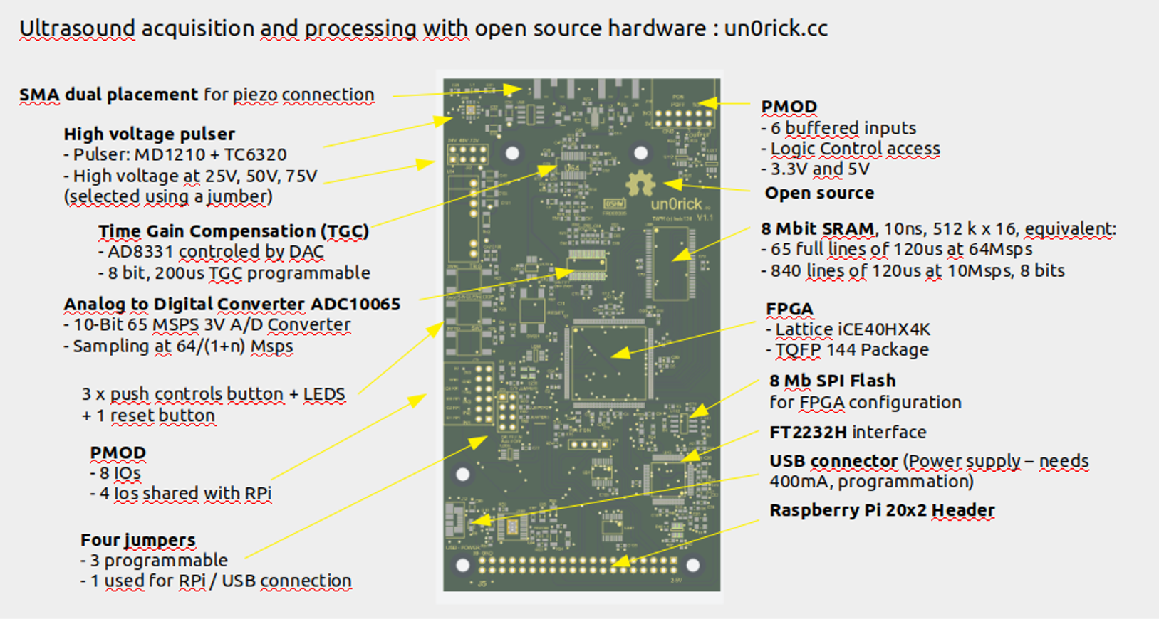
Specs (un0v1.1)
- FPGA: Lattice iCE40HX4K - TQFP 144 Package
- Memory:
- 8 Mbit SRAM, 10ns, 512 k x 16, equivalent to 65 full lines of 120us at 64Msps or 840 lines of 120us at 10Msps, 8 bits.
- 8 Mb SPI Flash for FPGA configuration
- Ultrasound processing:
- VGA: AD8331 controled by DAC
- Pulser: MD1210 + TC6320
- ADC: 65Msps ADC10065
- Data formatted over 2 bytes, with 10 bits / sample, 2 bits of line trackers, 4 bits of IOs (counters, …) and 2 bits for tracking.
- Parameters: Settings programable via USB or Raspberry Pi
- Type of acquisition (one line / set of lines)
- Number of lines
- Length of lines acquisitions
- Delay between acquisitions
- Pulse width
- Delay between pulse and beginning of acquisitions
- 200us time-gain-compensation programmable (8 bits, from 0 to Max), every 5us
- Extensibility:
- 2 x Pmod connectors
- SMA plug for transducers
- RPi GPIO
- User Interfaces:
- 2 x PMOD for IOs
- 4 x push button (with software noise debouncing)
- Jumpers for high voltage selection
- Jumpers for SPI selection
- Input Voltage:
- 5 V from RPi or USB
- Uses 350mA-450mA at 5V (including RPi)
- Operating Voltage:
- FPGA and logics at at 3.3 V
- High voltage at 25V, 50V, 75V
- Fully Open Source:
- Hardware: github repository
- Software: github repository
- Toolchain: Project IceStorm
- Documentation: gitbook
Latest sources
- Hardware resources are on github:
- FPGA bin so far using Lattice’s tools. A icestorm port is coming.
- Files for v1.1 and v1.01 are available - on upverter too.
- FPGA files too:
- Python lib too
Orders
- The board is available on Tindie at around 489$.
- Send me a mail at orders@un0rick.cc !
- Or wait for the Tindie shop
Others
Changelog
- lit3rick v1.4
- Using AD8332 for more gain
- ADC: 12bits -> 10bits
- lit3rick v1.3
- lighter board
- 12bits ADC
- up5k based
- external HV modules
- un0rick dual _v1.2 - to be done
- Better HV generation
- SPI muxing to update
- Check USB too
- PMOD-compliant headers
- remove i2c header, but keep i2c to RPI (with PU)
- un0rick dual - v1.1
- Double SMA to possibly separate TX and RX path (for dual elements transducers)
- Still some issues with muxing
- un0rick - v1.01
- Rewired SPI
- Less MUXing
- The “matty board” v1
- First ice40 board - compatible with iceprog =)
- Only one in existence, had some SPI wiring issues
- HV module footprint reversed
Useful links
- Come and chat : Want to learn more? We are on the Matrix as an open chat, if you want to discuss, but there are plenty of other sources:
- The full GitHub Repo for the hx8k board.
- The board’s Tindie shop
- The project Hackaday page
- A messy braindump with all experiments, and a slightly cleaner documentation of earlier works.
- un0rick boards are open-source certified on OSHWA, FR000005. lit3rick’s certification is done on OSHWA, FR000006.
- wlmeng11’s SimpleRick for a analog part board. Clever use of RTL-sdr hardware for the acquisition !
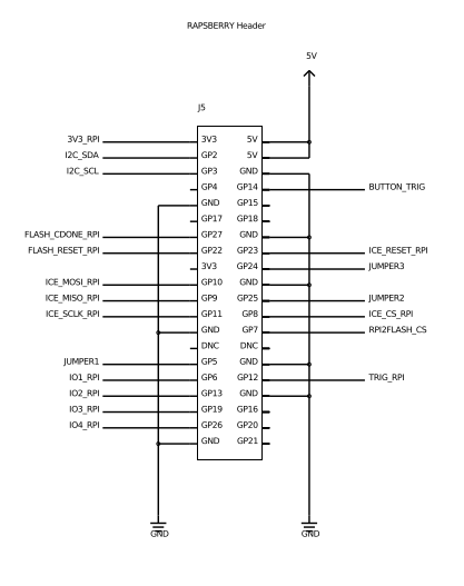
Pinouts
Raspberry Pi header
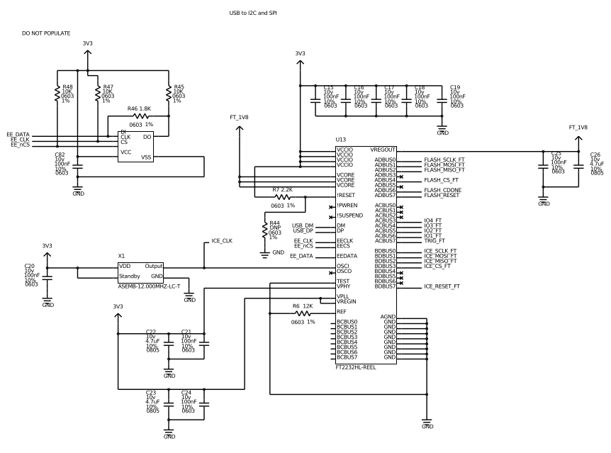
FTDI breakout
Thanks & shouts
- BiVi - always here to chat
- Charles - bringing neat insights
- David - what would I have done without you?
- echOmods - the fundations of this work
- Fabian - already so many insights
- Fouad.. and team - awesome works there
- Jan - piezooos
- Johannes and Felix - hardware is .. hard, but rew-harding!
- Sofian - early ideas!
- Sterling - another geek
- Tindie - to allow people sharing their niche hardware, and for others to search for these
- Visa - exploring amode
- Vlad - you pulse
- Wlmeng11 - inspiring
- All the supportive users
- .. and all the others around the world!

License
This work is based on a previous TAPR project, the echOmods project. The un0rick project and its boards are open hardware and software, developped with open-source elements.
Copyright Kelu124 (kelu124@gmail.com) 2018
- The hardware is licensed under TAPR Open Hardware License (www.tapr.org/OHL)
- The software components are free software: you can redistribute it and/or modify it under the terms of the GNU General Public License as published by the Free Software Foundation, either version 3 of the License, or (at your option) any later version.
- The documentation is licensed under a Creative Commons Attribution-ShareAlike 3.0 Unported License.
Disclaimer(s)
This project is distributed WITHOUT ANY EXPRESS OR IMPLIED WARRANTY, INCLUDING OF MERCHANTABILITY, SATISFACTORY QUALITY AND FITNESS FOR A PARTICULAR PURPOSE. See the GNU General Public License for more details. Also:
- This is not a medical ultrasound scanner! It’s a development kit that can be used for pedagogical and academic purposes - possible immediate use as a non-destructive testing (NDT) tool, for example in metallurgical crack analysis.
- As in all electronics, be careful, especially.
- This is a learning by doing project, I never did something related -> It’s all but a finalized product.
- Ultrasound raises questions. In case you build a scanner, use caution and good sense!