




minus
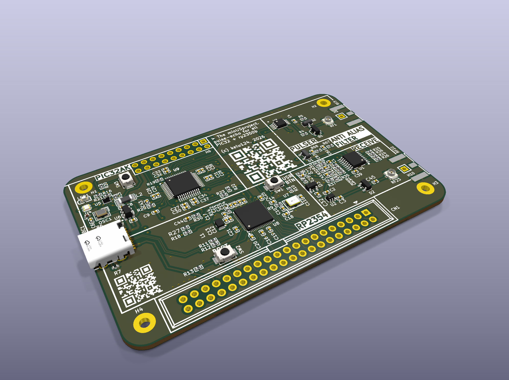
A minimal, single-channel, low-cost, open-source ultrasound pulse-echo platform, built as a conference-workshop badge.
minus drives one piezo transducer with a pulse, amplifies and digitizes the returning echo, and streams the raw data to a computer over USB-C. It is meant to be cheap, small, simple and hackable. Attendees of an ultrasound workshop can use it as-is (for example to monitor muscle contraction in A-mode or M-mode), then take it home and extend it: coded excitation, on-device DSP, add-on boards.
Status: working prototype (minus v1.1, board minUS_08112026). Pulse-echo, the switchable RX gain, the fixed-pattern correction and the RGB LED work on the bench. Firmware RP2354A 1.1.2, PIC32AK 1.1.0, link protocol 10. Non-clinical: for research, education and NDT only. This is not a medical device.
Specifications
Measured on the bench unless stated otherwise. The full figures, errata and test conditions are in the datasheet (rev 0.2, PDF).
| Parameter | Value |
|---|---|
| Controllers | Raspberry Pi RP2354A (USB, console, pulse timing, gain mux, LED, PIC programmer) + Microchip PIC32AK1216GC41048 (on-chip op amps, ADC, DMA capture) |
| ADC | 12-bit, 24.86 Msps (divider 4, default); 19.9 / 9.9 / 5.0 Msps with dividers 10 / 20 / 40 |
| Capture length | 4095 samples = 164.7 µs ≈ 12.7 cm depth in soft tissue (1540 m/s) |
| Pulser | 3-level (+5 V, active GND clamp, high-Z), TC4427/MIC4427 driven, phases programmable in 6.67 ns steps |
| Receive chain | Protected RX → 24 dB MMIC LNA (BGA2817) → two on-chip op-amp stages, 4 legs each via analog mux, ×1 bypass |
| Gain | 9 settings, 0 to 42.5 dB |
| Transducer | 3–4 MHz single-element piezo; separate TX and RX connectors (SMA + U.FL) |
| Echo (3.3 MHz test probe) | Centre 3.22 MHz, −6 dB band 2.88–3.55 MHz, axial resolution ≈ 0.6 mm |
| Interface | USB-C, CDC serial console with text commands |
| Power | USB bus powered (5 V) |
| Board | 85.7 × 54.0 mm, 4-layer, 1.6 mm, designed for JLCPCB assembly |
| Design files | KiCad, Gerbers, BOM and positions in the repository |
System architecture
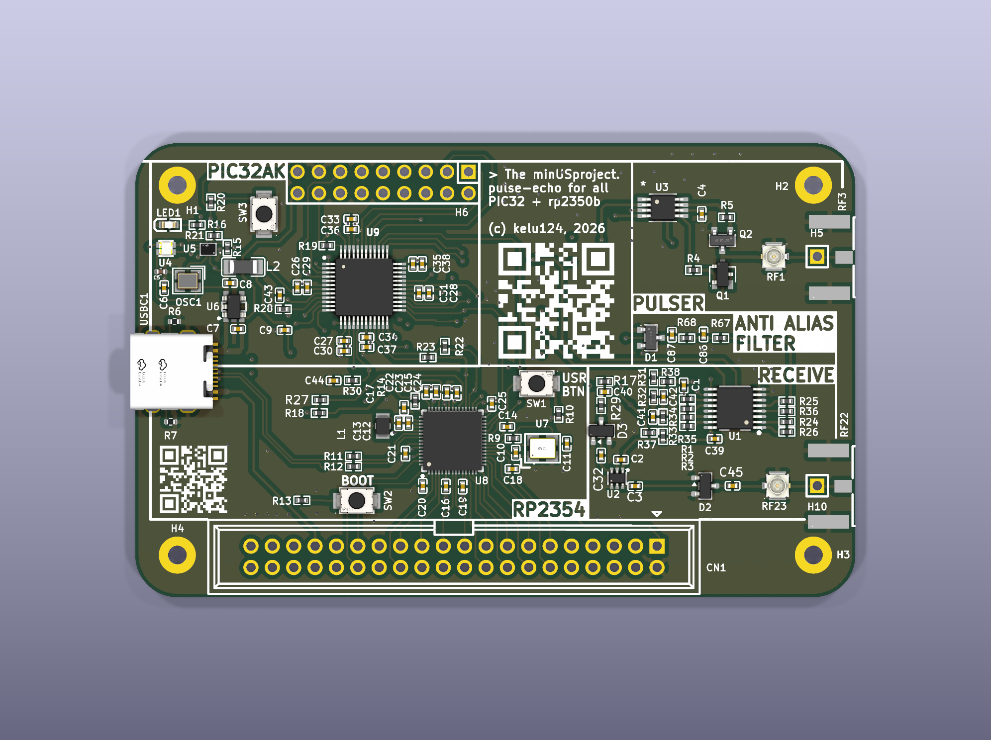
The board splits the work between two microcontrollers. The RP2354A owns USB, the command line, the pulser and the gain mux. The PIC32AK owns the two op-amp gain stages, the ADC and the DMA capture. The two talk over a serial link, and the RP2354A can also program the PIC in-system, so a single USB-C cable is enough to flash both.
RP2354A (PIO) → 3-level pulser → TX connector → piezo → echo
→ RX connector → protection → LNA → op-amp stage 1 → op-amp stage 2 → 12-bit ADC (PIC32AK)
→ DMA → serial link → RP2354A → USB-C → computer
Getting started
To flash the board you only need a USB-C cable. The firmware images are prebuilt and committed in the repository.
- RP2354A: hold BOOTSEL (SW2) and tap RUN (SW1). A UF2 drive appears: copy
firmware/rp2354/build/minus_rp.uf2onto it. - Console:
picocom /dev/ttyACM0, then typehelpandversion. - PIC32AK:
pic idto check the chip, thenpic flash. The RP2354A writes the PIC image embedded in its own firmware. - Link check:
pingshould answerok;rgb 0 255 0turns the LED green. - Pulse-echo:
pefires the pulser and captures one A-line;gain [leg [u1 [u2]]]sets the RX gain.
From Python:
from minus import Minus      # pip install -e python/library
dev = Minus()                # auto-detects the port
dev.gain(2, 0, 0)
a = dev.pe()                 # a.samples, a.t_us, a.depth_mm()
Step-by-step Jupyter notebooks walk through connecting, acquisition, gain, averaging and the front end. Building the firmware yourself (pico-sdk for the RP2354A, MPLAB XC-DSC for the PIC32AK) is covered in the repository README.
Known limitations
The full list is in the datasheet errata. The ones that matter when you use the data:
- Sample-comb phase: the pulse falls anywhere within one 40 ns sample from shot to shot, and in some captures the sampling slips by a whole sample. Align shots on the echo of interest before averaging.
- ADC slow lock: detected on the PIC;
peandacqre-shoot automatically. - Link speed: the MCUs talk at 115 200 Bd, so one 4095-sample shot takes about 0.9 s end to end.
- Separate TX and RX: a single-element probe on one connector needs an external tee for now.
How it fits in the family
| minus | pic0rick | |
|---|---|---|
| Status | Prototype | Active |
| Years | 2026– | 2024–now |
| Controller | RP2354A + PIC32AK | RP2040 / RP2350 |
| ADC | 12-bit, ~25 Msps (on-chip) | 10-bit, 60 Msps |
| Gain | 0–42.5 dB, 9 steps | AD8331 TGC, 7.5–55.5 dB |
| Pulser | +5 V, 3-level, on board | ±25 V, 3-level, PMOD + HV board |
| Form factor | Single badge-sized board | Main board + PMODs |
| Best for | Workshops, teaching, low-cost experiments | NDT, prototyping, deeper targets |
minus builds on the earlier open single-channel ultrasound work of the project: echOmods/Murgen, un0rick, lit3rick and pic0rick, reusing their proven building blocks.
Source files
Everything is in the minus repository:
- Hardware: KiCad project and JLCPCB production files in
hardware/ - Firmware: RP2354A (pico-sdk) and PIC32AK (XC-DSC) sources, with built images, in
firmware/ - Python: the
minuslibrary and notebooks inpython/ - Datasheet: LaTeX source and PDF in
datasheet/ - Bench data: measurement campaigns, raw captures and analysis scripts in
docs/bench/
Questions? Reach out on Slack or open an issue on GitHub.
License
- The hardware is licensed under the TAPR Open Hardware License v1.0 (www.tapr.org/OHL)
- The firmware, Python library and scripts are licensed under GPL-3.0-or-later
- The documentation, datasheet and bench data are licensed under CC-BY-SA-4.0
Details and third-party exceptions are in LICENSE.md. OSHWA certification is planned.
Disclaimer
This project is distributed WITHOUT ANY EXPRESS OR IMPLIED WARRANTY, INCLUDING OF MERCHANTABILITY, SATISFACTORY QUALITY AND FITNESS FOR A PARTICULAR PURPOSE.